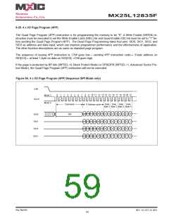
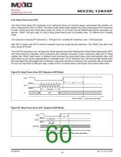
MX25L12835F
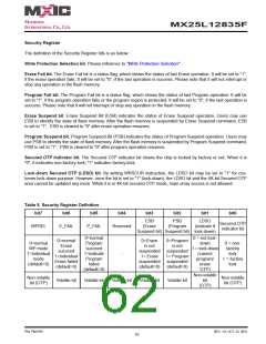
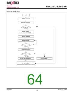
9-31. Write Protection Selection (WPSEL)
There are two write protection methods provided on this device, (1) Block Lock (BP) protection mode (2) Advance
Sector protection mode. If WPSEL=0, flash is under BP protection mode . If WPSEL=1, flash is under Advance Sec-
tor protection mode. The default value of WPSEL is “0”. WPSEL command can be used to set WPSEL=1. Please
note that WPSEL is an OTP bit. Once WPSEL is set to 1, there is no chance to recovery WPSEL back to “0”.
If the flash is put on BP mode, the Advance Sector protection mode is disabled. Contrarily, if flash is on the Advance
Sector protection mode, the BP mode is disabled.
Every time after the system is powered-on, and the Security Register bit 7 is checked to be WPSEL=1, all
the blocks or sectors will be write protected by Dynamic Protected Bit (DPB) in default. User may only unlock
the blocks or sectors via GBULK instruction. Program or erase functions can only be operated after the Unlock in-
struction is conducted.
When WPSEL = 0: Block Lock (BP) protection mode,
Array is protected by BP3~BP0 and BP bits are protected by “SRWD=1 and WP#=0”, where SRWD is bit 7 of status
register that can be set by WRSR command.
When WPSEL =1: Advance Sector protection mode,
Blocks are individually protected by their own SPB or DPB lock bits which are set to “1” after power up. When the
system accepts and executes WPSEL instruction, the bit 7 in security register will be set. It will activate WRLR,
RDLR, WRPASS, RDPASS, PASSULK, WRSPB, ESSPB, SPBLK, RDSPBLK, WRDPB, RDDPB, GBLK, GBULK
etc instructions to conduct block lock protection and replace the original Software Protect Mode (SPM) use (BP3~BP0)
indicated block methods. Under the Advance Sector protection mode (WPSEL=1), hardware protection is performed
by driving WP#=0. Once WP#=0 all array blocks/sectors are protected regardless of the contents of SPB or DPB
lock bits.
The sequence of issuing WPSEL instruction is: CS# goes low → sending WPSEL instruction to enter the individual
block protect mode → CS# goes high.
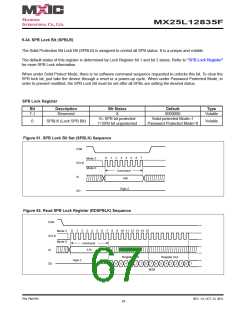
Write Protection Selection
Start
(Default in BP Mode)
WPSEL=1
WPSEL=0
Set
WPSEL Bit
Advance
Sector Protection
Block Protection
(BP)
Set
Bit 1 =0
Lock Register
Bit 2 =0
Password
Protection
Solid
Protection
Dynamic
Protection
P/N: PM1795
REV. 1.0, OCT. 23, 2012
63

 Macronix [ MACRONIX INTERNATIONAL ]