MX25L12835F
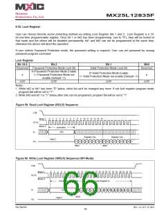
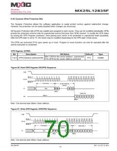
9-33. Lock Register
User can choose favorite sector protecting method via setting Lock Register bits 1 and 2 . Lock Register is a 16-
bit one-time programmable register. Once bit 1 or bit2 has been programming (set to "0"), they will be locked in
that mode and the others will be disabled permanently. bit1 and bit2 can not be programmed at the same time,
otherwise the device will abort the operation.
If user selects Password Protection mode, the password setting is required. User can set password by issuing
password program command.
Lock Register
Bit 15-3
Bit 2
Bit 1
Bit0
Reserved
Password Protection Mode Lock Bit
0=Password Protection Mode Enable
1= Password Protection Mode not
enable (Default =1)
Solid Protection Mode Lock Bit
Reserved
0=Solid Protection Mode Enable
1= Solid Protection Mode not enable (Default =1)
x
x
OTP
OTP
OTP
OTP
Notes:
1. While bit2 or bit1 has been "0" status, other bit can't be changed any more. If set lock register program mode,
program fail will be set to "1".
2. While bit2 and bit 1 is "1" status,other bits can be programed, program fail will be set to "1".
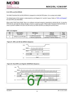
Figure 59. Read Lock Register (RDLR) Sequence
CS#
0
1
2
3
4
5
6
7
8
9 10 11 12 13 14 15
Mode 3
Mode 0
SCLK
SI
command
2Dh
Register Out
Register Out
High-Z
SO
7
6
5
4
3
2
1
0
7
6
5
4
3
2
1
0
7
MSB
MSB
Figure 60. Write Lock Register (WRLR) Sequence (SPI Mode)
CS#
0
1
2
3
4
5
6
7
8
9 10 11 12 13 14 15 16 17 18 19 20 21 22 23
Mode 3
Mode 0
SCLK
Command
2Ch
Lock Register In
SI
4
15 14
12 11
10
13
8
2
1
0
9
7
6
5
3
MSB
High-Z
SO
P/N: PM1795
REV. 1.0, OCT. 23, 2012
66

 Macronix [ MACRONIX INTERNATIONAL ]