MX25L12835F
Security Register
The definition of the Security Register bits is as below:
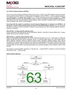
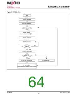
Write Protection Selection bit. Please reference to "Write Protection Selection"
Erase Fail bit. The Erase Fail bit is a status flag, which shows the status of last Erase operation. It will be set to "1",
if the erase operation fails. It will be set to "0", if the last operation is success. Please note that it will not interrupt or
stop any operation in the flash memory.
Program Fail bit. The Program Fail bit is a status flag, which shows the status of last Program operation. It will be
set to "1", if the program operation fails or the program region is protected. It will be set to "0", if the last operation is
success. Please note that it will not interrupt or stop any operation in the flash memory.
Erase Suspend bit. Erase Suspend Bit (ESB) indicates the status of Erase Suspend operation. Users may use
ESB to identify the state of flash memory. After the flash memory is suspended by Erase Suspend command, ESB
is set to "1". ESB is cleared to "0" after erase operation resumes.
Program Suspend bit. Program Suspend Bit (PSB) indicates the status of Program Suspend operation. Users may
use PSB to identify the state of flash memory. After the flash memory is suspended by Program Suspend command,
PSB is set to "1". PSB is cleared to "0" after program operation resumes.
Secured OTP Indicator bit. The Secured OTP indicator bit shows the chip is locked by factory or not. When it is
"0", it indicates non-factory lock; "1" indicates factory-lock.
Lock-down Secured OTP (LDSO) bit. By writing WRSCUR instruction, the LDSO bit may be set to "1" for cus-
tomer lock-down purpose. However, once the bit is set to "1" (lock-down), the LDSO bit and the 4K-bit Secured OTP
area cannot be updated any more. While it is in 4K-bit secured OTP mode, main array access is not allowed.
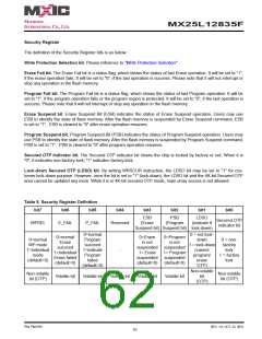
Table 9. Security Register Definition
bit7
bit6
bit5
bit4
bit3
bit2
bit1
bit0
ESB
(Erase
PSB
(Program
LDSO
(indicate if
Secured OTP
indicator bit
WPSEL
E_FAIL
P_FAIL
Reserved
Suspend bit) Suspend bit) lock-down)
0=normal
Program
succeed
1=indicate
Program
failed
0 = not lock-
0=normal
Erase
succeed
1=individual
Erase failed
(default=0)
0=Erase
is not
suspended suspended
1= Erase 1= Program
suspended suspended
0=Program
is not
0=normal
WP mode
1=individual
mode
down
1 = lock-down
(cannot
program/
erase
0 = non-
factory
lock
1 = factory
lock
-
(default=0)
(default=0)
(default=0)
(default=0)
OTP)
Non-volatile
bit
Non-volatile
bit (OTP)
Non-volatile
bit (OTP)
Volatile bit
Volatile bit
Volatile bit
Volatile bit
Volatile bit
(OTP)
P/N: PM1795
REV. 1.0, OCT. 23, 2012
62

 Macronix [ MACRONIX INTERNATIONAL ]