5V, Differential Input, DirectDrive, 130mW
Stereo Headphone Amplifiers with Shutdown
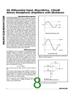
DirectDrive
Conventional single-supply headphone amplifiers have
MICROPHONE
BIAS
their outputs biased about a nominal DC voltage (typi-
cally half the supply) for maximum dynamic range.
MICROPHONE
AMPLIFIER
Large coupling capacitors are needed to block this DC
bias from the headphone. Without these capacitors, a
MICROPHONE
AMPLIFIER
significant amount of DC current flows to the head-
phone, resulting in unnecessary power dissipation and
OUTPUT
possible damage to both the headphone and the head-
phone amplifier.
Maxim’s DirectDrive architecture uses a charge pump to
AUDIO
INPUT
create an internal negative supply voltage, allowing the
MAX9722A/MAX9722B outputs to be biased about
GND. With no DC component, there is no need for the
large DC-blocking capacitors. Instead of two large
(220µF, typ) tantalum capacitors, the MAX9722A/
MAX9722B charge pump requires two small ceramic
MAX9722
AUDIO
INPUT
capacitors, conserving board space, reducing cost, and
improving the frequency response of the headphone
amplifier. See the Output Power vs. Load Resistance
graph in the Typical Operating Characteristics for
details of the possible capacitor sizes. There is a low
DC voltage on the amplifier outputs due to amplifier off-
set. However, the offset of the MAX9722A is typically
0.5mV, which, when combined with a 32Ω load, results
in less than 15.6µA of DC current flow to the head-
phones. Previous attempts to eliminate the output-cou-
pling capacitors involved biasing the headphone return
(sleeve) to the DC-bias voltage of the headphone ampli-
fiers. This method raises some issues:
HEADPHONE DRIVER
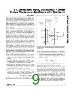
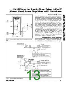
Figure 3. Earbud Speaker/Microphone Combination Headset
Configuration
phone amplifiers, these capacitors limit the amplifier’s
low-frequency response and can distort the audio signal:
1) The impedance of the headphone load and the DC-
blocking capacitor form a highpass filter with the
-3dB point set by:
• The sleeve is typically grounded to the chassis.
Using this biasing approach, the sleeve must be iso-
lated from system ground, complicating product
design.
1
f
=
• During an ESD strike, the amplifier’s ESD structures
are the only path to system ground. Thus, the amplifi-
er must be able to withstand the full ESD strike.
-3dB
2πR C
L
OUT
where R is the impedance of the headphone and
L
• When using the headphone jack as a line out to other
equipment, the bias voltage on the sleeve may con-
flict with the ground potential from other equipment,
resulting in possible damage to the amplifiers.
C
OUT
is the value of the DC-blocking capacitor.
The highpass filter is required by conventional single-
ended, single power-supply headphone amplifiers to
block the midrail DC-bias component of the audio sig-
nal from the headphones. The drawback to the filter is
that it can attenuate low-frequency signals. Larger val-
• When using a combination microphone and speaker
headset, the microphone typically requires a GND
reference. The amplifier DC bias on the sleeve con-
flicts with the microphone requirements (Figure 3).
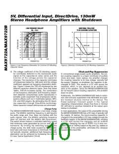
ues of C
reduce this effect but result in physically
OUT
larger, more expensive capacitors. Figure 4 shows the
relationship between the size of C and the resulting
Low-Frequency Response
In addition to the cost and size disadvantages of the DC-
blocking capacitors required by conventional head-
OUT
low-frequency attenuation. Note that the -3dB point for
a 16Ω headphone with a 100µF blocking capacitor is
100Hz, well within the normal audio band, resulting in
low-frequency attenuation of the reproduced signal.
_______________________________________________________________________________________
9

 MAXIM [ MAXIM INTEGRATED PRODUCTS ]