5V, Differential Input, DirectDrive, 130mW
Stereo Headphone Amplifiers with Shutdown
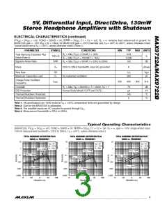
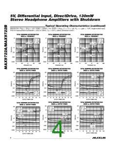
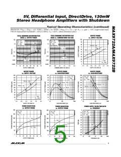
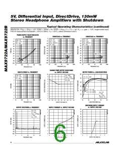
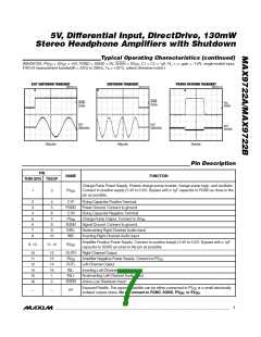
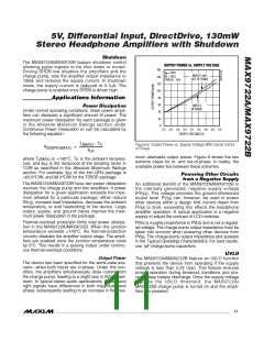
Typical Operating Characteristics (continued)
(MAX9722A, PV
= SV
= +5V, PGND = SGND = 0V, SHDN = SV , C1 = C2 = 1µF, R = ∞, gain = -1V/V, single-ended input,
DD DD L
DD
THD+N measurement bandwidth = 22Hz to 22kHz, T = +25°C, unless otherwise noted.)
A
EXIT SHUTDOWN TRANSIENT
SHUTDOWN TRANSIENT
POWER-UP/DOWN TRANSIENT
MAX9722 toc33
MAX9722 toc31
MAX9722 toc32
SHDN
2V/div
SHDN
2V/div
V
DD
2V/div
OUT
500mV/div
OUT
500mV/div
OUT
5mV/div
200μs/div
400μs/div
20ms/div
Pin Description
PIN
THIN QFN TSSOP
NAME
FUNCTION
Charge-Pump Power Supply. Powers charge-pump inverter, charge-pump logic, and oscillator.
Connect to positive supply (2.4V to 5.5V). Bypass with a 1µF capacitor to PGND as close to the
pin as possible.
1
3
PV
DD
2
3
4
5
6
7
8
4
5
C1P
PGND
C1N
Flying Capacitor Positive Terminal
Power Ground. Connect to ground.
Flying Capacitor Negative Terminal
6
7
PV
Charge-Pump Output. Connect to SV
Signal Ground. Connect to ground.
.
SS
SS
8
SGND
INR+
INR-
9
Noninverting Right-Channel Audio Input
Inverting Right-Channel Audio Input
10
Amplifier Positive Power Supply. Connect to positive supply (2.4V to 5.5V). Bypass with a 1µF
capacitor to SGND as close to the pin as possible.
9, 13
11, 15
SV
DD
10
11
12
14
15
16
12
13
14
16
1
OUTR
SV
Right-Channel Output
Amplifier Negative Power Supply. Connect to PV
.
SS
SS
OUTL
INL-
Left-Channel Output
Inverting Left-Channel Audio Input
Noninverting Left-Channel Audio Input
Active-Low Shutdown Input
INL+
SHDN
2
Exposed Paddle. The exposed paddle can be either connected to PV or a small electrically
SS
—
—
EP
isolated copper plane. Do not connect to PGND, SGND, PV , or SV
.
DD
DD
_______________________________________________________________________________________
7

 MAXIM [ MAXIM INTEGRATED PRODUCTS ]