Smallest TEC Power Drivers for
Optical Modules
The output common-mode ripple voltage can be calcu-
lated as follows:
bypassing may be needed to stabilize the input supply.
In such cases, a low-ESR electrolytic or ceramic capaci-
tor of 100µF or more at V is sufficient.
DD
V
= LIR x I
(ESR + 1/8 x C x fs)
TEC(MAX)
Compensation Capacitor
RIPPLE(P-P)
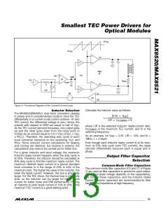
A compensation capacitor is needed to ensure current-
control-loop stability (see Figure 3). Select the capacitor
so that the unity-gain bandwidth of the current-control
loop is less than or equal to 10% the resonant frequency
of the output filter:
A 1µF ceramic capacitor with ESR of 10mΩ with LIR =
12% and I = 1.5A results in V of
24.3mV. For size-constraint applications, the capacitor
can be made smaller at the expense of higher ripple
voltage. However, the capacitance must be high
enough so that the LC resonant frequency is less than
1/5 the switching frequency:
TEC(MAX)
RIPPLE(P-P)
g
24×R
SENSE
m
C
≥
×
COMP
f
2π(R
×R
)
BW
SENSE
TEC
where:
= unity-gain bandwidth frequency, less than or
1
f =
f
BW
2π LC
equal to 10% the output filter resonant frequency
where f is the resonant frequency of the output filter.
g
m
= loop transconductance, typically 100µA/V
C
= value of the compensation capacitor
COMP
Differential Mode Filter Capacitor
The differential-mode filter capacitor (C5 in Figure 1) is
used to bypass differential ripple current through the
TEC as the result of unequal duty cycle of each output.
This happens when the TEC current is not at zero. As
TEC current increases from zero, both outputs move
away from the 50% duty-cycle point complementarily.
The common-mode ripple decreases, but the differential
ripple does not cancel perfectly, and there is a resulting
differential ripple. The maximum value happens when
one output is at 75% duty cycle and the other is at 25%
duty cycle. At this operating point, the differential ripple
is equal to 1/2 of the maximum common-mode ripple.
The TEC ripple current determines the TEC perfor-
mance, because the maximum temperature differential
that can be created between the terminals of the TEC
depends on the ratio of ripple current and DC current.
The lower the ripple current, the closer to the ideal
maximum. The differential-mode capacitor provides a
low-impedance path for the ripple current to flow, so that
the TEC ripple current is greatly reduced. The TEC ripple
current can then be calculated as follows:
R
TEC
= TEC series resistance; use the minimum resis-
tance value
R
= sense resistor
SENSE
Setting Voltage and Current Limits
Certain TEC parameters must be considered to guarantee
a robust design. These include maximum positive current,
maximum negative current, and the maximum voltage
allowed across the TEC. These limits should be used to
set the MAXIP, MAXIN, and MAXV voltages.
Setting Max Positive and Negative TEC Current
MAXIP and MAXIN set the maximum positive and nega-
tive TEC currents, respectively. The default current limit
is 150mV/R
when MAXIP and MAXIN are con-
SENSE
nected to REF. To set maximum limits other than the
defaults, connect a resistor-divider from REF to GND to
set V
. Use resistors in the 10kΩ to 100kΩ range.
MAXI_
V
is related to ITEC by the following equations:
MAXI_
V
= 10(I
= 10(I
✕ R )
SENSE
MAXIP
MAXIN
TECP(MAX)
TECN(MAX)
V
✕ R
)
SENSE
I
= (0.5 x LIR x I
) x (Z )/(R
TEC(RIPPLE)
TEC(MAX) C5 TEC
where I
and I
is the maximum positive TEC current
TECP(MAX)
+ R
+ Z
)
SENSE
C5
is the negative maximum TEC current.
TECN(MAX)
where Z is the impedance of C5 at twice the switching
Positive TEC current occurs when CS is less than OS1:
C5
frequency, R
is the TEC equivalent resistance, and
TEC
I
x R
= OS1 - CS
TEC
SENSE
R
is the current-sense resistor.
SENSE
when I
when I
> 0.
TEC
TEC
Decoupling Capacitor Selection
I
✕ R
= CS - OS1
TEC
SENSE
Decouple each power-supply input (V , PV 1,
DD
DD
< 0.
PV 2) with a 1µF ceramic capacitor close to the supply
DD
pins. In applications with long distances between the
source supply and the MAX8520/MAX8521, additional
14 ______________________________________________________________________________________

 MAXIM [ MAXIM INTEGRATED PRODUCTS ]