Smallest TEC Power Drivers for
Optical Modules
3/4 V
DD
1/4 V
DD
LX2
-1.2
PWM
4X
1.2X
REF
COMP
gm
CTLI
R
SENSE
1
C
COMP
LX1
R
R
+1.2
0.5X
REF
CS
10X
OS1
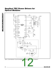
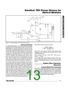
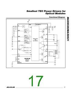
Figure 3. Functional Diagram of the Current-Control Loop
Calculate the inductor value as follows:
Inductor Selection
The MAX8520/MAX8521 dual buck converters operate
in phase and in complementary mode to drive the TEC
differentially in a current-mode control scheme. At zero
TEC current, the differential voltage is zero; hence, the
0.25 × V
(
)
DD
L =
LIR × I
× fs
TEC(MAX)
outputs with respect to GND are equal to half of V
.
DD
where LIR is the selected inductor ripple-current ratio,
As the TEC current demand increases, one output goes
up and the other goes down from the initial point of
I
is the maximum TEC current, and fs is the
TEC(MAX)
switching frequency.
0.5V
by an amount equal to 0.5 ✕ V
(V
= I
DD
TEC TEC TEC
). Therefore, the operating duty cycle of each
As an example, for V
1MHz, L = 4.58µH.
= 3.3V, LIR = 12%, and fs =
DD
✕ R
TEC
buck converter depends on the operating I
and
TEC
Even though each inductor ripple current is at its maxi-
mum at 50% duty cycle (zero TEC current), the ripple
cancels differentially because each is equal and in
phase.
R
. Since inductor current calculations for heating
TEC
and cooling are identical, but reverse in polarity, the
calculations only need to be carried out for either one.
For a given inductor and input voltage, the maximum
inductor ripple current happens when the duty cycle is
at 50%. Therefore, the inductor should be calculated at
50% duty cycle to find the maximum ripple current. The
maximum desired ripple current of a typical standard
buck converter is in the range of 20% to 40% of the
maximum load. The higher the value of the inductor, the
lower the ripple current. However, the size is physically
larger. For the TEC driver, the thermal loop is inherently
slow, so the inductor can be larger for lower ripple
current for better noise and EMI performance. Picking
an inductor to yield ripple current of 10% to 20% of the
maximum TEC current is a good starting point.
Output Filter Capacitor
Selection
Common-Mode Filter Capacitors
The common-mode filter capacitors (C2 and C7 of Figure
1) are used as filter capacitors to ground for each output.
The output ripple voltage depends on the capacitance,
the ESR of these capacitors, and the inductor ripple
current. Ceramic capacitors are recommended for their
low ESR and impedance at high frequency.
______________________________________________________________________________________ 13

 MAXIM [ MAXIM INTEGRATED PRODUCTS ]