NiCd /NiMH Ba t t e ry
Fa s t -Ch a rg e Co n t ro lle rs
2/MAX713
The MAX712/MAX713 can be configured so that voltage
slope and/or battery temperature detects full charge.
the voltage on the battery pack is higher during a fast-
charge cycle than while in trickle charge or while supply-
ing a load. The voltage across some battery packs may
approach 1.9V/cell.
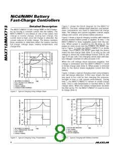
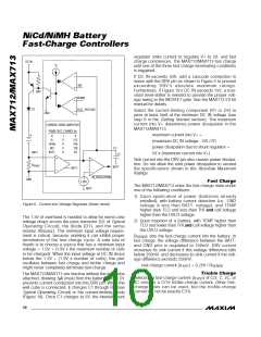
Figure 4 shows a charging event in which a battery is
inserted into an already powered-up MAX712/MAX713.
During time 1, the charger’s output voltage is regulated
at the number of cells times VLIMIT. Upon insertion of
the battery (time 2), the MAX712/MAX713 detect cur-
rent flow into the battery and switch to fast-charge
state. Once full charge is detected, the device reverts
to trickle charge (time 3). If the battery is removed (time
4), the MAX712/MAX713 remain in trickle charge and
the output voltage is once again regulated as in time 1.
Q1
D1
DC IN
R2
R1
2N3904
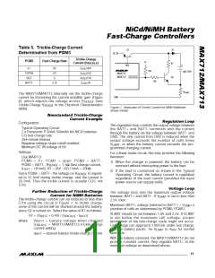
P o w e rin g t h e MAX7 1 2 /MAX7 1 3
AC-to-DC wall-cube adapters typically consist of a trans-
former, a full-wave bridge rectifier, and a capacitor.
Figures 10–12 show the characteristics of three con-
sumer product wall cubes. All three exhibit substantial
120Hz output voltage ripple. When choosing an adapter
for use with the MAX712/MAX713, make sure the lowest
wall-cube voltage level during fast charge and full load is
at least 1.5V higher (2V for switch mode) than the maxi-
mum battery voltage while being fast charged. Typically,
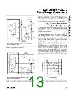
V+
DRV
MAX712
MAX713
Figure 5. DRV Pin Cascode Connection (for high DC IN voltage
or to reduce MAX712/MAX713 power dissipation in linear mode)
†
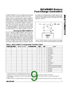
Table 4. MAX712/MAX713 Charge-State Transition Table
POWER_ON_RESET
UNDER_VOLTAGE
IN_REGULATION
COLD
HOT
Result*
0
↑
↑
↑
↑
↑
x
1
x
x
x
0
0
0
↓
x
x
1
x
x
0
0
0
0
↓
x
x
x
0
x
1
1
↓
x
x
x
x
0
1
1
1
1
1
↑
Set trickle
No change
No change
No change
No change***
Set fast
1
1
1
1
1
1
1
1
1
1
1
No change
No change
1
1
1
↑
Set fast
0
0
0
x
x
↑
Set fast
0
0
x
x
0
↑
x
No change***
Set fast**
1
x
0
x
x
↓
0
x
x
x
x
Trickle to fast transition inhibited
Trickle to fast transition inhibited
Set trickle
0
x
Set trickle
Set trickle
† Only two states exist: fast charge and trickle charge.
* Regardless of the status of the other logic lines, a timeout or a voltage-slope detection will set trickle charge.
** If the battery is cold at power-up, the first rising edge on COLD will trigger fast charge; however, a second rising edge will
have no effect.
***Batteries that are too hot when inserted (or when circuit is powered up) will not enter fast charge until they cool and power is recycled.
_______________________________________________________________________________________
9

 MAXIM [ MAXIM INTEGRATED PRODUCTS ]