NiCd /NiMH Ba t t e ry
Fa s t -Ch a rg e Co n t ro lle rs
2/MAX713
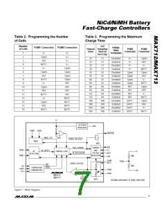
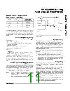
Table 5. Trickle-Charge Current
Determination from PGM3
Q1
D1
DC IN
Trickle-Charge
Current (I
PGM3
Fast-Charge Rate
V+
)
TRICKLE
R7
DRV
V+
4C
2C
C
I
/64
/32
/16
FAST
10k
BATTERY
OPEN
REF
I
FAST
MAX712
MAX713
Q2
FASTCHG
I
FAST
10k
BATT-
C/2
I
/8
FAST
R
SENSE
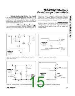
The MAX712/MAX713 internally set the trickle-charge
current by increasing the current amplifier gain (Figure
GND
6), whic h a d jus ts the volta g e a c ros s R
(s e e
SENSE
Trickle-Charge V
table).
in the Electrical Characteristics
SENSE
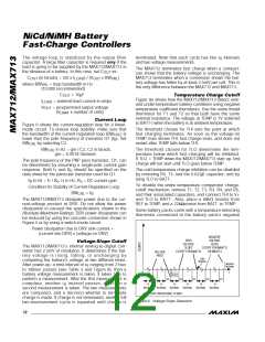
Figure 7. Reduction of Trickle Current for NiMH Batteries
(linear mode)
No n s t a n d a rd Tric k le -Ch a rg e
Cu rre n t Ex a m p le
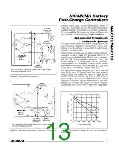
Re g u la t io n Lo o p
Configuration:
The regulation loop controls the output voltage between
the BATT+ a nd BATT- te rmina ls a nd the c urre nt
through the battery via the voltage between BATT- and
GND. The sink current from DRV is reduced when the
outp ut volta g e e xc e e d s the numb e r of c e lls time s
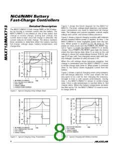
Typical Operating Circuit
2 x Panasonic P-50AA 500mAh AA NiCd batteries
C/3 fast-charge rate
264-minute timeout
Negative voltage-slope cutoff enabled
Minimum DC IN voltage of 6V
V
, or when the battery current exceeds the pro-
LIMIT
grammed charging current.
Settings:
For a linear-mode circuit, this loop provides the following
functions:
Use MAX713
PGM0 = V+ , PGM1 = op e n, PGM2 = BATT-,
1) When the charger is powered, the battery can be
removed without interrupting power to the load.
PGM3 = BATT-, R
= 1.5Ω (fast-charge current,
SENSE
I
= 167mA), R1 = (6V - 5V) / 5mA = 200Ω
FAST
2) If the load is connected as shown in the Typical
Operating Circuit, the battery current is regulated
regardless of the load current (provided the input
power source can supply both).
Since PGM3 = BATT-, the voltage on R
is regulat-
SENSE
ed to 31.3mV during trickle charge, and the current is
20.7mA. Thus the trickle current is actually C/25, not
C/16.
Vo lt a g e Lo o p
The voltage loop sets the maximum output voltage
Fu rt h e r Re d u c t io n o f Tric k le -Ch a rg e
Cu rre n t fo r NiMH Ba t t e rie s
between BATT+ and BATT-. If V
is set to less than
LIMIT
The trickle-charge current can be reduced to less than
C/16 using the circuit in Figure 7. In trickle charge,
some of the current will be shunted around the battery,
since Q2 is turned on. Select the value of R7 as follows:
2.5V, then:
Maximum BATT+ voltage (referred to BATT-) = V
(number of cells as determined by PGM0, PGM1)
x
LIMIT
VLIMIT should be set between 1.9V and 2.5V. If VLIMIT
is s e t b e low the ma ximum c e ll volta g e , p rop e r
termination of the fast-charge cycle might not occur.
Cell voltage can approach 1.9V/cell, under fast charge,
in some battery packs. Tie V
operation .
R7 = (V
+ 0.4V) / (l
- I
)
BATT
TRlCKLE BATT
where
V
BATT
= b a tte ry volta g e whe n c ha rg e d
I
= MAX712/MAX713 trickle-charge
TRlCKLE
current setting
to V
for normal
LIMIT
REF
I
= desired battery trickle-charge current
BATT
With the battery removed, the MAX712/MAX713 do not
provide constant current; they regulate BATT+ to the
maximum voltage as determined above.
______________________________________________________________________________________ 11

 MAXIM [ MAXIM INTEGRATED PRODUCTS ]