NiCd /NiMH Ba t t e ry
Fa s t -Ch a rg e Co n t ro lle rs
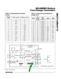
and PGM1 must be adjusted accordingly. Attempting
to charge more or fewer cells than the number pro-
grammed can disable the voltage-slope fast-charge
termination circuitry. The internal ADC’s input volt-
age range is limited to between 1.4V and 1.9V (see
the Electrical Characteristics), and is equal to the
voltage across the battery divided by the number of
cells programmed (using PGM0 and PGM1, as in
Table 2). When the ADC’s input voltage falls out of
its specified range, the voltage-slope termination cir-
cuitry can be disabled.
____________________Ge t t in g S t a rt e d
The MAX712/MAX713 are simple to use. A complete
linear-mode or switch-mode fast-charge circuit can be
designed in a few easy steps. A linear-mode design
uses the fewest components and supplies a load while
charging, while a switch-mode design may be neces-
sary if lower heat dissipation is desired.
1) Follow the battery manufacturer’s recommendations
on maximum charge currents and charge-termination
methods for the specific batteries in your application.
Table 1 provides general guidelines.
4) Choose an external DC power source (e.g., wall
cube). Its minimum output voltage (including ripple)
must be greater than 6V and at least 1.5V higher (2V
for switch mode) than the maximum battery voltage
while charging. This specification is critical because
normal fast-charge termination is ensured only if this
re q uire me nt is ma inta ine d (s e e Powe ring the
MAX712/MAX713 section for more details).
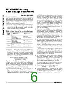
Table 1. Fast-Charge Termination Methods
Charge
Rate
NiMH Batteries
NiCd Batteries
2/MAX713
∆V/∆t and
temperature,
MAX712 or MAX713
∆V/∆t and/or
temperature, MAX713
> 2C
5) For linear-mode designs, calculate the worst-case
power dissipation of the power PNP and diode (Q1
and D1 in the Typical Operating Circuit) in watts,
using the following formula:
∆V/∆t and/or
temperature,
MAX712 or MAX713
∆V/∆t and/or
temperature, MAX713
2C to C/2
< C/2
PD
= (ma ximum wa ll-c ub e volta g e und e r
PNP
∆V/∆t and/or
temperature, MAX712
∆V/∆t and/or
temperature, MAX713
load - minimum battery voltage) x (charge current
in amps)
If the maximum power dissipation is not tolerable for
your application, refer to the Detailed Description or
us e a s witc h-mod e d e s ig n (s e e Switc h-Mod e
Operation in the Applications Information section,
and see the MAX713 EV kit manual).
2) Decide on a charge rate (Tables 3 and 5). The slow-
est fast-charge rate for the MAX712/MAX713 is C/4,
because the maximum fast-charge timeout period is
264 minutes. A C/3 rate charges the battery in about
three hours. The current in mA required to charge at
this rate is calculated as follows:
6) For both linear and switch-mode designs, limit cur-
rent into V+ to between 5mA and 20mA. For a fixed
or narrow-range input voltage, choose R1 in the
Typical Operation Circuit using the following formula:
I
= (capacity of battery in mAh)
–––––––––––––––––––––––––
(charge time in hours)
FAST
R1 = (minimum wall-cube voltage - 5V) / 5mA
Depending on the battery, charging efficiency can be
as low as 80%, so a C/3 fast charge could take 3 hours
and 45 minutes. This reflects the efficiency with which
electrical energy is converted to chemical energy within
the b a tte ry, a nd is not the s a me a s the p owe r-
conversion efficiency of the MAX712/MAX713.
For designs requiring a large input voltage variation,
choose the current-limiting diode D4 in Figure 19.
7) Choose R
using the following formula:
SENSE
RSENSE = 0.25V / (I
)
FAST
8) Consult Ta ble s 2 a nd 3 to se t pin-stra ps be fore
applying power. For example, to fast charge at a
rate of C/2, set the timeout to between 1.5x or 2x the
charge period, three or four hours, respectively.
3) Decide on the number of cells to be charged (Table 2).
If your battery stack exceeds 11 cells, see the Linear-
Mode High Series Cell Count section. Whenever
changing the number of cells to be charged, PGM0
6
_______________________________________________________________________________________

 MAXIM [ MAXIM INTEGRATED PRODUCTS ]