NiCd /NiMH Ba t t e ry
Fa s t -Ch a rg e Co n t ro lle rs
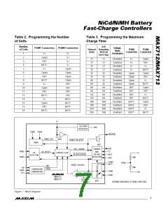
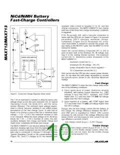
Figure 1 shows the block diagram for the MAX712/
MAX713. The timer, voltage-slope detection, and temper-
ature comparators are used to determine full charge
state. The voltage and current regulator controls output
voltage and current, and senses battery presence.
_______________De t a ile d De s c rip t io n
The MAX712/MAX713 fast charge NiMH or NiCd batter-
ies by forcing a constant current into the battery. The
MAX712/MAX713 are always in one of two states: fast
c ha rg e or tric kle c ha rg e . During fa s t c ha rg e , the
current level is high; once full charge is detected, the
current reduces to trickle charge. The device monitors
three variables to determine when the battery reaches
full charge: voltage slope, battery temperature, and
charge time.
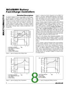
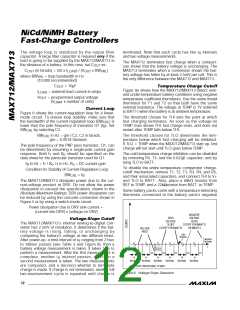
Figure 2 shows a typical charging scenario with batteries
already inserted before power is applied. At time 1, the
MAX712/MAX713 draw negligible power from the bat-
tery. When power is applied to DC IN (time 2), the
power-on reset circuit (see the POWER_ON_RESET sig-
nal in Figure 1) holds the MAX712/MAX713 in trickle
charge. Once POWER_ON_RESET goes high, the device
enters the fast-charge state (time 3) as long as the cell
voltage is above the undervoltage lockout (UVLO) volt-
age (0.4V per cell). Fast charging cannot start until (bat-
tery voltage) / (number of cells) exceeds 0.4V.
1.5
1.4
VOLTAGE
1.3
TEMPERATURE
2/MAX713
When the cell voltage slope becomes negative, fast
charge is terminated and the MAX712/MAX713 revert
to trickle-charge state (time 4). When power is removed
(time 5), the device draws negligible current from the
battery.
0.4
0
A
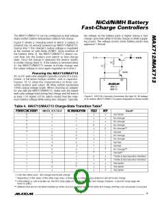
Figure 3 shows a typical charging event using tempera-
ture full-charge detection. In the case shown, the bat-
tery pack is too cold for fast charging (for instance,
brought in from a cold outside environment). During
time 2, the MAX712/MAX713 remain in trickle-charge
state. Once a safe temperature is reached (time 3), fast
charge starts. When the battery temperature exceeds
the limit set by THI, the MAX712/MAX713 revert to trick-
le charge (time 4).
mA
µA
4
1
2
3
5
1. NO POWER TO CHARGER
2. CELL VOLTAGE LESS THAN 0.4V
3. FAST CHARGE
4. TRICKLE CHARGE
5. CHARGER POWER REMOVED
TIME
Figure 2. Typical Charging Using Voltage Slope
VREF = VLIMIT
THI
1.5
1.4
1.3
TLO
A
A
mA
mA
µA
µA
1
2
3
4
1
2
3
4
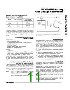
1. BATTERY NOT INSERTED
2. FAST CHARGE
3. TRICKLE CHARGE
4. BATTERY REMOVED
TIME
1. NO POWER TO CHARGER
2. CELL TEMPERATURE TOO LOW
3. FAST CHARGE
TIME
4. TRICKLE CHARGE
Figure 3. Typical Charging Using Temperature
Figure 4. Typical Charging with Battery Insertion
8
_______________________________________________________________________________________

 MAXIM [ MAXIM INTEGRATED PRODUCTS ]