NiCd /NiMH Ba t t e ry
Fa s t -Ch a rg e Co n t ro lle rs
regulator sinks current to regulate V+ to 5V, and fast
charge commences. The MAX712/MAX713 fast charge
until one of the three fast-charge terminating conditions
is triggered.
DC IN
V+
If DC IN exceeds 20V, add a cascode connection in
series with the DRV pin as shown in Figure 5 to prevent
e xc e e d ing DRV’s a b s olute ma ximum ra ting s .
Furthermore, if Figure 19’s DC IN exceeds 15V, a tran-
sistor level-shifter is needed to provide the proper volt-
age swing to the MOSFET gate. See the MAX713 EV kit
manual for details.
REF
DRV
VLIMIT
D1
CELL_VOLTAGE
Select the current-limiting component (R1 or D4) to
pass at least 5mA at the minimum DC IN voltage (see
step 6 in the Getting Started section). The maximum
current into V+ determines power dissipation in the
MAX712/MAX713.
GND
CURRENT-SENSE AMPLIFIER
PGM3 FAST_CHARGE Av
2/MAX713
maximum current into V+ =
X
V+
OPEN
REF
1
0
0
0
0
8
512
256
128
64
(maximum DC IN voltage - 5V) / R1
power dissipation due to shunt regulator =
5V x (maximum current into V+)
CC
C2
BATT-
BATT-
Sink current into the DRV pin also causes power dissipa-
tion. Do not allow the total power dissipation to exceed
the spe c ific a tions shown in the Ab solute Ma ximum
Ratings.
R
SENSE
BATT-
BATT-
IN_REGULATION
GND
Fa s t Ch a rg e
The MAX712/MAX713 enter the fast-charge state under
one of the following conditions:
1.25V
BATT-
1) Up on a p p lic a tion of p owe r (b a tte rie s a lre a d y
installed), with battery current detection (i.e., GND
volta g e is le s s tha n BATT- volta g e ), a nd TEMP
higher than TLO and less than THI and cell voltage
higher than the UVLO voltage.
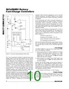
Figure 6. Current and Voltage Regulator (linear mode)
The 1.5V of overhead is needed to allow for worst-case
voltage drops across the pass transistor (Q1 of Typical
Op e ra ting Circ uit), the d iod e (D1), a nd the s e ns e
2) Upon insertion of a battery, with TEMP higher than
TLO and lower than THI and cell voltage higher than
the UVLO voltage.
resistor (R ). This minimum input voltage require-
SENSE
ment is critical, because violating it can inhibit proper
termination of the fast-charge cycle. A safe rule of
thumb is to choose a source that has a minimum input
voltage = 1.5V + (1.9V x the maximum number of cells
to be charged). When the input voltage at DC IN drops
below the 1.5V + (1.9V x number of cells), the part
oscillates between fast charge and trickle charge and
might never completely terminate fast-charge.
R
sets the fast-charge current into the battery. In
SENSE
fast charge, the voltage difference between the BATT-
and GND pins is regulated to 250mV. DRV current
increases its sink current if this voltage difference falls
below 250mV, and decreases its sink current if the volt-
age difference exceeds 250mV.
fast-charge current (I ) = 0.25V / R
FAST SENSE
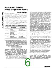
Tric k le Ch a rg e
) of C/2, C, 2C, or
4C ensures a C/16 trickle-charge current. Other fast-
c ha rg e ra te s c a n b e us e d , b ut the tric kle -c ha rg e
current will not be exactly C/16.
The MAX712/MAX713 are inactive without the wall cube
attached, drawing 5µA (max) from the battery. Diode D1
prevents current conduction into the DRV pin. When the
wall cube is connected, it charges C1 through R1 (see
Typical Operating Circuit) or the current-limiting diode
(Figure 19). Once C1 charges to 5V, the internal shunt
Selecting a fast-charge current (I
FAST
10 ______________________________________________________________________________________

 MAXIM [ MAXIM INTEGRATED PRODUCTS ]