NiCd /NiMH Ba t t e ry
Fa s t -Ch a rg e Co n t ro lle rs
2/MAX713
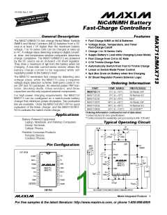
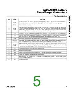
______________________________________________________________P in De s c rip t io n
PIN
1
NAME
VLIMIT
BATT+
FUNCTION
Sets the maximum cell voltage. The battery terminal voltage (BATT+ - BATT-) will not exceed VLIMIT x
(number of cells). Do not allow VLIMIT to exceed 2.5V. Tie VLIMIT to VREF for normal operation.
2
Positive terminal of battery
PGM0 and PGM1 set the number of series cells to be charged. The number of cells can be set from
1 to 16 by connecting PGM0 and PGM1 to any of V+, REF, or BATT-, or by leaving the pin open (Table
2). For cell counts greater than 11, see the Linear-Mode, High Series Cell Count section. Charging more
or fewer cells than the number programmed may inhibit ∆V fast-charge termination.
PGM0,
PGM1
3, 4
5
6
7
8
THI
TLO
Trip point for the over-temperature comparator. If the voltage-on TEMP rises above THI, fast charge ends.
Trip point for the under-temperature comparator. If the MAX712/MAX713 power on with the voltage-on
TEMP less than TLO, fast charge is inhibited and will not start until TEMP rises above TLO.
TEMP
Sense input for temperature-dependent voltage from thermistors.
Open-drain, fast-charge status output. While the MAX712/MAX713 fast charge the battery, FASTCHG
sinks current. When charge ends and trickle charge begins, FASTCHG stops sinking current.
FASTCHG
PGM2 and PGM3 set the maximum time allowed for fast charging. Timeouts from 33 minutes to 264
minutes can be set by connecting to any of V+, REF, or BATT-, or by leaving the pin open (Table 3).
PGM3 also sets the fast-charge to trickle-charge current ratio (Table 5).
PGM2,
PGM3
9, 10
11
12
13
14
CC
Compensation input for constant current regulation loop
Negative terminal of battery
BATT-
GND
DRV
System ground. The resistor placed between BATT- and GND monitors the current into the battery.
Current sink for driving the external PNP current source
Shunt regulator. The voltage on V+ is regulated to +5V with respect to BATT-, and the shunt current
powers the MAX712/MAX713.
15
16
V+
REF
2V reference output
_______________________________________________________________________________________
5

 MAXIM [ MAXIM INTEGRATED PRODUCTS ]