NiCd /NiMH Ba t t e ry
Fa s t -Ch a rg e Co n t ro lle rs
The voltage-slope, fast-charge termination circuitry
mig ht b e c ome d is a b le d if a tte mp ting to c ha rg e a
different number of cells than the number programmed.
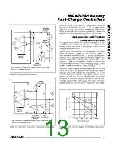
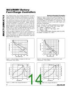
Ba t t e ry-Ch a rg in g Ex a m p le s
Figures 13 and 14 show the results of charging 3 AA,
1000mAh, NiMH batteries from Gold Peak (part no.
GP1000AAH, GP Batteries (619) 438-2202) at a 1A rate
us ing the MAX712 a nd MAX713, re s p e c tive ly. The
Typ ic a l Op e ra ting Circ uit is us e d with Fig ure 9a ’s
thermistor configuration .
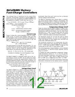
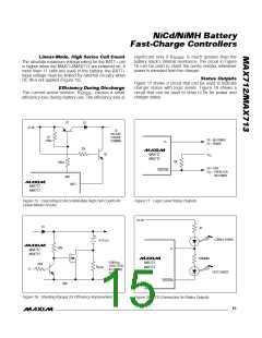
The switching frequency (nominally 30kHz) can be
decreased by increasing the value of the capacitor
connected between CC and BATT-. Make sure that
the two c a p a c itors c onne c te d to the CC nod e a re
p la c e d a s c los e a s p os s ib le to the CC p in on the
MAX712/MAX713 and that their leads are of minimum
length. The CC node is a high-impedance point, so do
not route logic lines near the CC pin. The circuit of
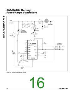
Figure 19 cannot service a load while charging.
DC IN = Sony AC-190 +9VDC at 800mA AC-DC adapter
PGM0 = V+, PGM1 = REF, PGM2 = REF, PGM3 = REF
R1 = 200Ω, R2 = 150Ω, R
= 0.25Ω
SENSE
C1 = 1µF, C2 = 0.01µF, C3 = 10µF, V
= REF
LIMIT
R3 = 10kΩ, R4 = 15kΩ
T1, T2 = part #13A1002 (Alpha Thermistor: (800) 235-5445)
R5 omitted, T3 omitted, TLO = BATT-
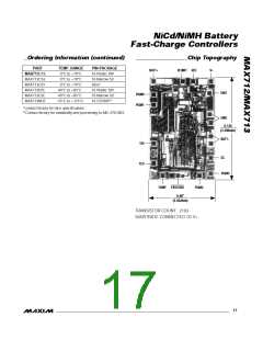
Order the MAX713SWEVKIT-SO for quick evaluation of
the MAX712/MAX713 in switch-mode operation. For
more informa tion on s witc h-mod e op e ra tion a nd
ordering information for external components, order the
MAX713EVKIT data sheet.
2/MAX713
18
16
11
10
HIGH PEAK
9
14
HIGH PEAK
8
12
120Hz
RIPPLE
LOW PEAK
7
6
5
LOW PEAK
600
10
120Hz
RIPPLE
8
0
200
400
600
800
0
200
400
800
1000
LOAD CURRENT (mA)
LOAD CURRENT (mA)
Figure 11. Sony CD Player AC Adapter AC-96N Load
Characteristic, 9VDC 600mA
Figure 12. Panasonic Modem AC Adapter KX-A11 Load
Characteristic, 12VDC 500mA
5.0
4.9
4.8
4.7
4.6
4.5
4.4
4.3
4.2
5.0
4.9
4.8
4.7
4.6
4.5
4.4
4.3
4.2
40
38
36
34
32
30
28
26
24
40
38
36
34
32
30
28
26
24
∆V
∆t
∆V
∆t
CUTOFF
CUTOFF
V
V
T
T
0
30
TIME (MINUTES)
60
90
0
30
TIME (MINUTES)
60
90
Figure 13. 3 NiMH Cells Charged with MAX712
14 ______________________________________________________________________________________
Figure 14. NiMH Cells Charged with MAX713

 MAXIM [ MAXIM INTEGRATED PRODUCTS ]