NiCd /NiMH Ba t t e ry
Fa s t -Ch a rg e Co n t ro lle rs
2/MAX713
significant only if R
is much greater than the
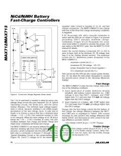
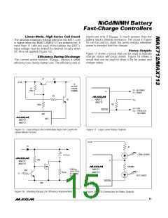
Lin e a r-Mo d e , Hig h S e rie s Ce ll Co u n t
The absolute maximum voltage rating for the BATT+ pin
is higher when the MAX712/MAX713 are powered on. If
more than 11 cells are used in the battery, the BATT+
input voltage must be limited by external circuitry when
DC IN is not applied (Figure 15).
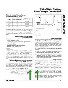
SENSE
battery stack’s internal resistance. The circuit in Figure
16 can be used to shunt the sense resistor whenever
power is removed from the charger.
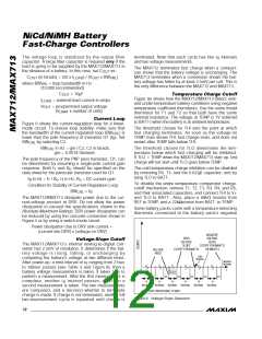
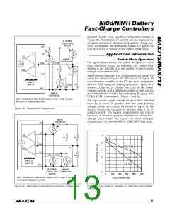
S t a t u s Ou t p u t s
Figure 17 shows a circuit that can be used to indicate
charger status with logic levels. Figure 18 shows a
circuit that can be used to drive LEDs for power and
charger status.
Effic ie n c y Du rin g Dis c h a rg e
The current-sense resistor, R
, causes a small
SENSE
efficiency loss during battery use. The efficiency loss is
Q1
D1
DC IN
TO
BATTERY
POSITIVE
TERMINAL
R2
150Ω
OV = NO POWER
5V = POWER
V+
33k
Q2
MAX712
MAX713
V
CC
MAX712
MAX713
10k
500Ω
OV = FAST
FASTCHG
V
= TRICKLE OR
CC
NO POWER
DRV
BATT+
MAX712
MAX713
Figure 15. Cascoding to Accommodate High Cell Counts for
Linear-Mode Circuits
Figure 17. Logic-Level Status Outputs
DC IN
D1
R1
CHARGE POWER
>4 CELLS
100k
V+
MAX712
MAX713
*
470ΩMIN
*LOW R
ON
LOGIC LEVEL
N-CHANNEL
POWER
MAX712
MAX713
100k
R
SENSE
V+
FAST CHARGE
MOSFET
FASTCHG
GND
Figure 16. Shunting R
for Efficiency Improvement
Figure 18. LED Connection for Status Outputs
SENSE
______________________________________________________________________________________ 15

 MAXIM [ MAXIM INTEGRATED PRODUCTS ]