2 -Wire S e ria l 8 -Bit DACs w it h
Ra il-t o -Ra il Ou t p u t s
78/MAX519
1
1
or or
0 AD3 AD2 AD1AD0 0
(RST) (PD)
0 0 0 1 1 0
(a)
SDA
0
1
0
INTERRUPTED
COMMAND BYTE
ADDRESS BYTE
ACK
EARLY
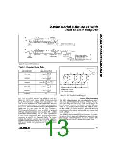
MAX517/MAX518/MAX519's
START
STOP CONDITION STATE REMAINS UNCHANGED.
(
CONDITION
)
1
1
or or
0 AD3 AD2AD1AD0 0
(b)
SDA
(PD)
0 RST 1
0
1
0
0
0
0
0
0
0
1
1
1
0
0
X
X
INTERRUPTED
OUTPUT BYTE
ADDRESS BYTE
ACK
COMMAND BYTE
(POWER DOWN)
ACK
MAX517/MAX518/MAX519
POWER DOWN; INPUT LATCH
UNCHANGED IF RST = 0,
START
CONDITION
EARLY
STOP CONDITION
(
)
DAC OUTPUT(S) RESET IF RST = 1.
Figure 14. Early STOP Conditions
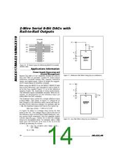
Table 1. Unipolar Code Table
DAC CONTENTS
ANALOG OUTPUT
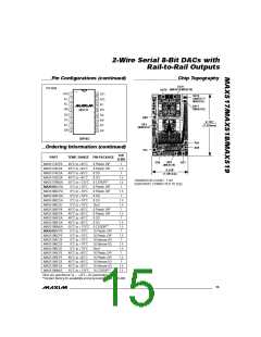
R
R
R
255
+ VREF (———)
256
OUT_
11111111
2R
2R
D0
2R
D5
2R
D6
2R
D7
129
+ VREF (———)
256
10000001
10000000
01111111
128
+ VREF (———) = ——
256
V
REF
2
REF_*
GND
127
+ VREF (———)
256
SHOWN FOR ALL 1s ON DAC
*REF = V FOR THE MAX518
1
+ VREF (———)
256
00000001
00000000
DD
0V
Figure 15. DAC Simplified Circuit Diagram
age, both DC and AC signals. The voltage at each REF
input sets the full-scale output voltage for its respective
DAC. The re fe re nc e volta g e mus t b e p os itive . The
DAC’s input impedance is code dependent, with the
lowest value occurring when the input code is 55 hex or
0101 0101, and the maximum value occurring when the
input code is 00 hex. Since the REF input resistance
(RIN) is code dependent, it must be driven by a circuit
with low output impedance (no more than RIN ÷ 2000)
to maintain output linearity. The REF input capacitance
is a ls o c od e d e p e nd e nt, with the ma ximum va lue
occurring at code FF hex (typically 30pF). The output
voltage for any DAC can be represented by a digitally
Output Buffer Amplifiers
The DAC voltage outputs are internally buffered preci-
sion unity-gain followers that slew up to 1V/µs. The out-
puts can swing from 0V to V . With a 0V to 4V (or 4V
DD
to 0V) output transition, the amplifier outputs typically
settle to 1/2LSB in 6µs when loaded with 10kΩ in paral-
lel with 100pF. The buffer amplifiers are stable with any
combination of resistive loads ≥2kΩ and capacitive
loads ≤300pF.
The MAX517/MAX518/MAX519 are designed for unipo-
lar-output, single-quadrant multiplication where the out-
put voltages and the reference inputs are positive with
respect to AGND. Table 1 shows the unipolar code.
programmable voltage source as: V
= (N x V ) /
OUT
REF
256, where N is the numerical value of the DAC’s binary
input code.
______________________________________________________________________________________ 13

 MAXIM [ MAXIM INTEGRATED PRODUCTS ]