2 -Wire S e ria l 8 -Bit DACs w it h
Ra il-t o -Ra il Ou t p u t s
latches with data that has not been transferred to the
output latches (Figure 13). Only the currently addressed
device will recognize a STOP condition and transfer
data to its output latches. If the device is left with data in
its input latches, the data can be transferred to the out-
put latches the next time the device is addressed, as
long as it receives at least one command byte and a
STOP condition.
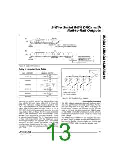
2
µC
E PROM
XICOR
X24C04
SDA SCL
SCL
SDA
Early STOP Conditions
The addressed device recognizes a STOP condition at
any point in a transmission. If the STOP occurs during a
command byte, all previous uninterrupted command
and output byte pairs are accepted, the interrupted
command byte is ignored, and the transmission ends
(Figure 14a). If the STOP occurs during an output byte,
all previous uninterrupted command and output byte
DUAL
DAC
OUT0
OUT1
MAX518
SCL
SDA
AD0
AD1
pairs are accepted, the final command byte’s PD and
RST bits are accepted, the interrupted output byte is
ignored, and the transmission ends (Figure 14b).
SINGLE
DAC
OUT0
+5V
An a lo g S e c t io n
MAX517
SCL
SDA
AD0
AD1
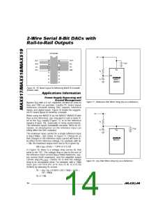
DAC Operation
The MAX518 and MAX519 contain two matched volt-
age-output DACs. The MAX517 contains a single DAC.
The DACs are inverted R-2R ladder networks that con-
vert 8-bit digital words into equivalent analog output
voltages in proportion to the applied reference volt-
ages. The MAX518 has both DAC’s reference inputs
78/MAX519
Figure 12. MAX517/MAX518/MAX519 Used in a Typical I2C
Application Circuit
connected to V . Figure 15 shows a simplified dia-
DD
gram of one DAC.
Additional START Conditions
It is possible to interrupt a transmission to a device with
a ne w START (re p e a te d s ta rt) c ond ition (p e rha p s
addressing another device), which leaves the input
MAX517/MAX519 Reference Inputs
The MAX517 and MAX519 can be used for multiplying
applications. The reference accepts a 0V to V
volt-
DD
0
1
0
1
1
0
0
0
0
0
0
0
0
0
0
0
0
0
1
1
1
1
1
1
1
1
0
1
0
1
1
0
1
0
0
0
SDA
START
ADDRESS BYTE
(DEVICE 0)
ACK
COMMAND BYTE
ADDRESSING DAC0
ACK
OUTPUT BYTE
(FULL SCALE)
ACK
ADDRESS BYTE
(DEVICE 1)
ACK
CONDITION
DEVICE 0's
DAC0 INPUT LATCH
SET TO FULL SCALE.
REPEATED START
CONDITION
(
)
0
0
0
0
0
0
0
0
0
1
1
1
1
1
1
1
1
0
SDA
ACK
OUTPUT BYTE
(FULL SCALE)
ACK
COMMAND BYTE
(ADDRESSING DAC0)
STOP
CONDITION
DEVICE 1's DAC0
INPUT LATCH SET
TO FULL SCALE.
ONLY DEVICE 1's DAC0 OUTPUT LATCH SET TO FULL
SCALE. DEVICE 0's OUTPUT LATCH UNCHANGED.
(
)
(
)
Figure 13. Repeated START Conditions
12 ______________________________________________________________________________________

 MAXIM [ MAXIM INTEGRATED PRODUCTS ]