Low-Cost Multichemistry Battery Chargers
Choose crossover frequency f
to be 1/5th the
where:
CO_CS
MAX1908/MAX8724 switching frequency:
t
= 2.5µs × (V
– V ) / V
BATT DCIN
OFF
DCIN
V
< 0.88 × V
BATT
DCIN
GMS
f
=
= 80kHz
CO_CS
or:
2πC
CS
t
= 0.3µs
OFF
Solving for C , C = 2nF.
CS CS
V
> 0.88 × V
DCIN
BATT
To be conservative, set C
crossover frequency at:
= 10nF, which sets the
CS
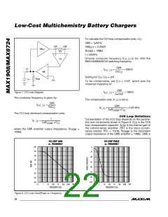
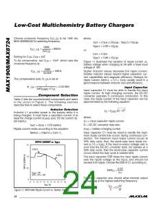
Figure 11 illustrates the variation of ripple current vs.
battery voltage when charging at 3A with a fixed input
voltage of 19V.
GMS
2π10nF
f
=
= 16kHz
Higher inductor values decrease the ripple current.
Smaller inductor values require higher saturation cur-
rent capabilities and degrade efficiency. Designs for
ripple current, I
good balance between inductor size and efficiency.
CO_CS
The compensation pole, f
is set at:
P_CS
= 0.3 × I
usually result in a
RIPPLE
CHG
1
f
=
= 0.0016Hz
P_CS
Input Capacitor
Input capacitor C1 must be able to handle the input
ripple current. At high charging currents, the DC-DC
converter operates in continuous conduction. In this
case, the ripple current of the input capacitor can be
approximated by the following equation:
2πR
×C
CS
OGMS
Component Selection
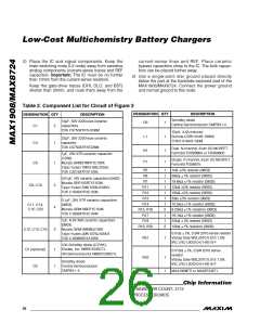
Table 2 lists the recommended components and refers
to the circuit of Figure 2. The following sections
describe how to select these components.
Inductor Selection
Inductor L1 provides power to the battery while it is
being charged. It must have a saturation current of at
2
I
= I
D − D
C1 CHG
where:
= input capacitor ripple current.
least the charge current (I
), plus 1/2 the current rip-
CHG
I
ple I
:
C1
RIPPLE
D = DC-DC converter duty ratio.
= battery-charging current.
I
= I
+ (1/2) I
CHG RIPPLE
SAT
I
Ripple current varies according to the equation:
CHG
Input capacitor C1 must be sized to handle the maxi-
mum ripple current that occurs during continuous con-
duction. The maximum input ripple current occurs at
50% duty cycle; thus, the worst-case input ripple cur-
I
= (V
) × t
/ L
RIPPLE
BATT
OFF
RIPPLE CURRENT vs. V
BATT
rent is 0.5 × I
. If the input-to-output voltage ratio is
CHG
1.5
1.0
0.5
0
such that the DC-DC converter does not operate at a
50% duty cycle, then the worst-case capacitor current
occurs where the duty cycle is nearest 50%.
3 CELLS
4 CELLS
The input capacitor ESR times the input ripple current
sets the ripple voltage at the input, and should not
exceed 0.5V ripple. Choose the ESR of C1 according to:
0.5V
ESR
<
C1
I
V
DCIN
= 19V
C1
VCTL = ICTL = LDO
The input capacitor size should allow minimal output
voltage sag at the highest switching frequency:
8
9
10 11 12 13 14 15 16 17 18
(V)
V
BATT
I
dV
dt
C1
2
= C1
Figure 11. MAX1908 Ripple Current vs. Battery Voltage
24 ______________________________________________________________________________________

 MAXIM [ MAXIM INTEGRATED PRODUCTS ]