Low-Cost Multichemistry Battery Chargers
To calculate the CCI loop compensation pole, C :
CI
GMI = 1µA/mV
CSIP
CSIN
GM
= 3.33A/V
OUT
GM
OUT
R
= 10MΩ
OGMI
RS2
CSI
f = 400kHz
Choose crossover frequency f
to be 1/5th the
CI
CO_
MAX1908/MAX8724 switching frequency:
GMI
CCI
C
f
=
= 80kHz
CO_CI
2πC
GMI
CI
Solving for C , C = 2nF.
CI CI
R
OGMI
CI
ICTL
To be conservative, set C = 10nF, which sets the
CI
crossover frequency at:
GMI
2π10nF
f
=
= 16kHz
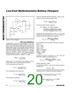
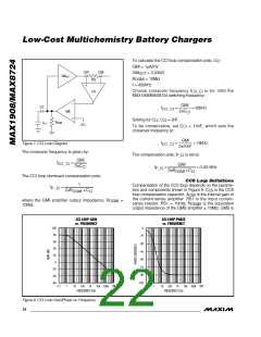
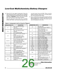
Figure 7. CCI Loop Diagram
CO_CI
The crossover frequency is given by:
GMI
The compensation pole, f
is set at:
P_CI
f
=
CO_CI
GMI
2πC
CI
f
=
= 0.0016Hz
P_CI
2πR
×C
CI
OGMI
The CCI loop dominant compensation pole:
1
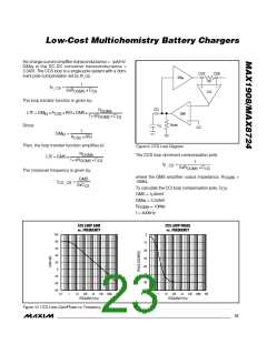
CCS Loop Definitions
Compensation of the CCS loop depends on the parame-
f
=
P _CI
ters and components shown in Figure 9. C is the CCS
CS
2πR
× C
CI
OGMI
loop compensation capacitor. A
is the internal gain of
CSS
the current-sense amplifier. RS1 is the input current-
where the GMI amplifier output impedance, R
10MΩ.
=
OGMI
sense resistor, RS1 = 10mΩ. R
output impedance of the GMS amplifier ≥ 10MΩ. GMS is
is the equivalent
OGMS
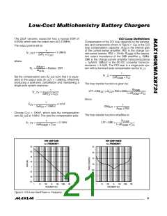
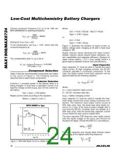
CCI LOOP GAIN
vs. FREQUENCY
CCI LOOP PHASE
vs. FREQUENCY
100
0
80
60
-15
-30
40
-45
20
-60
0
-75
-20
-40
-60
-90
-105
0.1
1
10 100 1k
FREQUENCY (Hz)
10k 100k 1M
0.1
1
10 100 1k
FREQUENCY (Hz)
10k 100k 1M
Figure 8. CCI Loop Gain/Phase vs. Frequency
22 ______________________________________________________________________________________

 MAXIM [ MAXIM INTEGRATED PRODUCTS ]