Low-Cost Multichemistry Battery Chargers
In normal operation, the controller starts a new cycle by
turning on the high-side N-channel MOSFET and
turning off the low-side N-channel MOSFET. When the
charge current is greater than the control point (LVC),
CCMP goes high and the off-time is started. The
off-time turns off the high-side N-channel MOSFET and
turns on the low-side N-channel MOSFET. The opera-
tional frequency is governed by the off-time and is
Discontinuous Conduction
The MAX1908/MAX8724 enter discontinuous-conduction
mode when the output of the LVC control point falls below
0.15V. For RS2 = 0.015Ω, this corresponds to 0.5A:
0.15V
20×RS2
I
=
= 0.5A for RS2 = 0.015Ω
MIN
dependent upon V
and V
. The off-time is set
BATT
DCIN
In discontinuous mode, a new cycle is not started until
the LVC voltage rises above 0.15V. Discontinuous-
mode operation can occur during conditioning charge
of overdischarged battery packs, when the charge cur-
rent has been reduced sufficiently by the CCS control
loop, or when the battery pack is near full charge (con-
stant voltage charging mode).
by the following equations:
V
− V
DCIN
BATT
t
= 2.5µs ×
OFF
t
V
DCIN
L ×I
RIPPLE
− V
BATT
=
ON
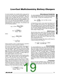
MOSFET Drivers
The low-side driver output DLO switches between
PGND and DLOV. DLOV is usually connected through
a filter to LDO. The high-side driver output DHI is boot-
V
CSSN
where:
strapped off LX and switches between V and V
.
BST
LX
V
× t
OFF
L
BATT
I
=
When the low-side driver turns on, BST rises to one
diode voltage below DLOV.
RIPPLE
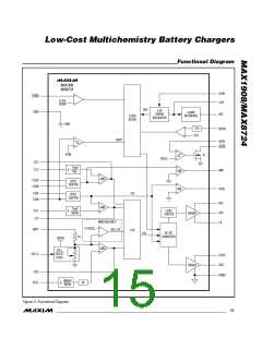
Filter DLOV with a lowpass filter whose cutoff frequency
is approximately 5kHz (Figure 1):
1
+ t
f =
t
ON
OFF
1
1
f =
=
= 4.8kHz
C
2πRC 2π × 33Ω ×1µF
These equations result in fixed-frequency operation
over the most common operating conditions.
Dropout Operation
At the end of the fixed off-time, another cycle begins if
the control point (LVC) is greater than 0.15V, IMIN =
high, and the peak charge current is less than 6A (RS2
= 0.015Ω), IMAX = high. If the charge current exceeds
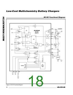
The MAX1908/MAX8724 have 99% duty-cycle capability
with a 5ms (max) on-time and 0.3µs (min) off-time. This
allows the charger to achieve dropout performance limit-
ed only by resistive losses in the DC-DC converter com-
ponents (D1, N1, RS1, and RS2, Figure 1). Replacing
diode D1 with a P-channel MOSFET driven by ACOK
improves dropout performance (Figure 2). The dropout
voltage is set by the difference between DCIN and CSIN.
When the dropout voltage falls below 100mV, the charger
is disabled; 200mV hysteresis ensures that the charger
does not turn back on until the dropout voltage rises to
300mV.
I
, the on-time is terminated by the IMAX comparator.
MAX
IMAX governs the maximum cycle-by-cycle current limit
and is internally set to 6A (RS2 = 0.015Ω). IMAX pro-
tects against sudden overcurrent faults.
If during the off-time the inductor current goes to zero,
ZCMP = high, both the high- and low-side MOSFETs
are turned off until another cycle is ready to begin.
There is a minimum 0.3µs off-time when the (V
-
DCIN
≥ 0.88 ×
V
V
) differential becomes too small. If V
BATT
DCIN
BATT
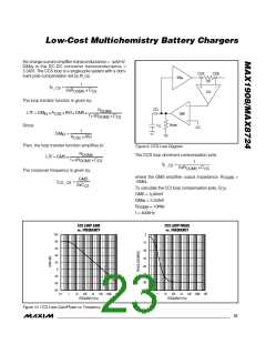
Compensation
Each of the three regulation loops—input current limit,
charging current limit, and charging voltage limit—are
compensated separately using CCS, CCI, and CCV,
respectively.
, then the threshold for minimum off-time is
is fixed at 0.3µs. A maximum on-
reached and the t
OFF
time of 5ms allows the controller to achieve >99% duty
cycle in continuous-conduction mode. The switching
frequency in this mode varies according to the equation:
1
f =
L ×I
RIPPLE
+ 0.3µs
V
− V
CSSN
BATT
______________________________________________________________________________________ 19

 MAXIM [ MAXIM INTEGRATED PRODUCTS ]