MAX17047/MAX17050
ModelGauge m3 Fuel Gauge
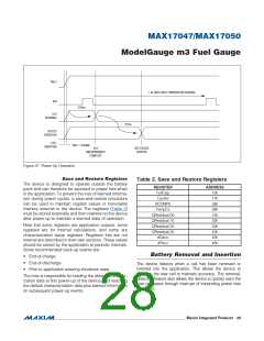
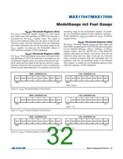
V
BATT
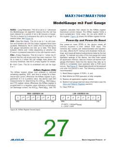
1.4s UNTIL NEXT TEMPERATURE READING
AIN
270ms
A/D
READINGS
175ms
OUTPUT
REGISTERS
CELL
INSERTION
V
BATT
> V
DDMIN
A/D
SOC VALUES
UPDATED
MEASUREMENTS
COMPLETE
Figure 37. Power-Up Operation
Save and Restore Registers
The device is designed to operate outside the battery
pack and can therefore be exposed to power loss when
in the application. To prevent the loss of learned informa-
tion during power cycles, a save-and-restore procedure
can be used to maintain register values in nonvolatile
memory external to the device. The registers (Table 2)
must be stored externally and then rewritten to the device
after power-up to maintain a learned state of operation.
Table 2. Save and Restore Registers
REGISTER
FullCap
ADDRESS
10h
Cycles
17h
RCOMP0
TempCo
38h
39h
QResidual 00
QResidual 10
QResidual 20
QResidual 30
dQacc
12h
22h
Note that some registers are application outputs, some
registers are for internal calculations, and some are
characterization setup registers. Registers that are not
internal are described in their own sections. These values
should be stored by the application at periodic intervals.
Some recommended back-up events are:
32h
42h
45h
dPacc
46h
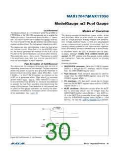
Battery Removal and Insertion
•ꢀ End-of-charge
•ꢀ End-of-discharge
The device detects when a cell has been removed or
inserted into the application. This allows the device to
adjust to the new cell to maintain accuracy. The removal-
detection feature also allows the device to quickly warn the
host processor through interrupt of impending power loss
if enabled.
•ꢀ Priorꢀtoꢀapplicationꢀenteringꢀshutdownꢀstate
The host is responsible for loading the default character-
ization data at first power-up of the device, and restoring
the default characterization data plus learned information
on subsequent power-up events.
���������������������������������������������������������������� Maxim Integrated Products 28

 MAXIM [ MAXIM INTEGRATED PRODUCTS ]