MAX17047/MAX17050
ModelGauge m3 Fuel Gauge
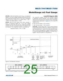
dV4:dV0—Sets the threshold, which V
is compared
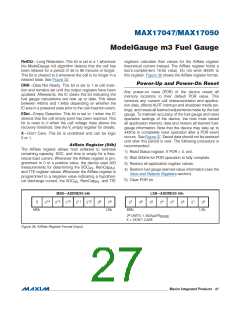
LearnCFG Register (28h)
The LearnCFG register controls all functions relating
to adaptation during operation. The LearnCFG register
default values should not be changed unless specifically
required by the application. Figure 33 is the LearnCFG
register format:
CELL
against. If the cell’s voltage changes by less than dV over
two consecutive periods set by dt, the cell is considered
relaxed; dV has a range of 0 to 40mV where 1 LSb =
1.25mV. The default value is 1.75mV.
dt3:dt0—Sets the time period over which change in
V
is compared against dV. If the cell’s voltage
0—Bit must be written 0. Do not write 1.
1—Bit must be written 1. Do not write 0.
CELL
changes by less than dV over two consecutive periods
set by dt, the cell is considered relaxed. The default value
is 6 minutes. The comparison period is calculated as:
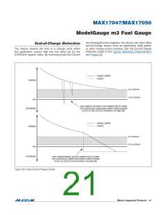
Filt Empty—Empty Detect Filter. This bit selects whether
empty is detected by a filtered or unfiltered voltage read-
ing. Setting this bit to 1 causes the empty detection algo-
dt
Relaxation Period = 2 O 0.1758s
rithm to use the AverageV
register. Setting this bit to
CELL
0 forces the empty detection algorithm to use the V
register. This bit is written to 0 at power-up.
CELL
0
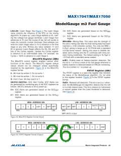
RELAXATION LOAD THRESHOLD
AVERAGE
CURRENT
DISCHARGING
dV6
dV5
dV4
CELL
VOLTAGE
dV3
dV2
48 TO 96
MINUTES
dt1
dt2
dt3
dt4
dt5
dt6
FIRST
READING
BELOW
dv/dt
THRESHOLD
SECOND
READING
BELOW
dV/dt
THRESHOLD
CELL IS RELAXED
RelDt BIT SET
CELL CAPACITY IS
LEARNED
LONG RELAXATION
RelDt2 BIT SET
CELL UNLOADED
(RELAXATION BEGINS)
Figure 32. Cell Relaxation Detection
MSB—ADDRESS
LSB—ADDRESS
Filt
Empty
2
1
0
0
0
1
0
0
1
1
0
0
LS
LS
LS
0
1
0
MSb
LSb
MSb
LSb
Figure 33. LearnCFG Register Format (Input/Output)
���������������������������������������������������������������� Maxim Integrated Products 25

 MAXIM [ MAXIM INTEGRATED PRODUCTS ]