MAX11329–MAX11332
3Msps, 12-/10-Bit, 8-/16-Channel ADCs with
Post-Mux External Signal Conditioning Access
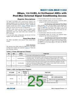
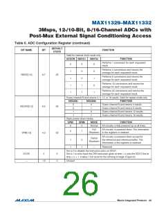
Table 6. ADC Configuration Register (continued)
DEFAULT
STATE
BIT NAME
BIT
FUNCTION
Valid for internal clock mode only.
AVGON NAVG1
NAVG0
FUNCTION
Performs 1 conversion for each requested
result.
0
1
1
1
1
X
0
0
1
1
X
Performs 4 conversions and returns the
average for each requested result.
0
1
0
1
NAVG[1:0]
8:7
00
Performs 8 conversions and returns the
average for each requested result.
Performs 16 conversions and returns the
average for each requested result.
Performs 32 conversions and returns the
average for each requested result.
Scans channel N and returns 4, 8, 12, or 16 results. Valid for repeat mode only.
NSCAN1
NSCAN0
FUNCTION
0
0
1
1
0
1
0
1
Scans channel N and returns 4 results.
Scans channel N and returns 8 results.
Scans channel N and returns 12 results.
Scans channel N and returns 16 results.
NSCAN[1:0]
6:5
00
Static power-down modes
SPM1
SPM0
MODE
Normal
Full
FUNCTION
0
0
All circuitry is fully powered up at all times.
All circuitry is powered down. The information
0
1
Shutdown in the registers is retained.
SPM[1:0]
4:3
00
All circuitry is powered down except for
the reference and reference buffer. The
information in the registers is retained.
Partial
Shutdown
1
1
0
1
—
Reserved
Set to 0 to disable the instruction echo on DOUT.
ECHO
—
2
0
0
Set to 1 to echo back the DIN instruction given at time = n onto the DOUT line at
time = n + 1. It takes 1 full cycle for the echoing to begin (Figure 8).
1:0
Unused
���������������������������������������������������������������� Maxim Integrated Products 26

 MAXIM [ MAXIM INTEGRATED PRODUCTS ]