MAX11329–MAX11332
3Msps, 12-/10-Bit, 8-/16-Channel ADCs with
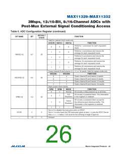
Post-Mux External Signal Conditioning Access
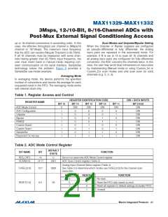
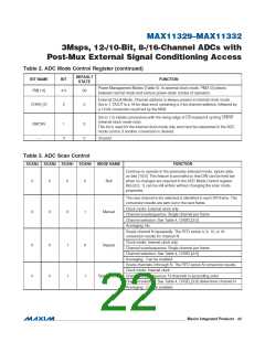
Table 2. ADC Mode Control Register (continued)
DEFAULT
STATE
BIT NAME
BIT
FUNCTION
Power Management Modes (Table 5). In external clock mode, PM[1:0] selects
between normal mode and various power-down modes of operation.
PM[1:0]
4:3
00
External Clock Mode. Channel address is always present in internal clock mode.
Set to 1, DOUT is a 16-bit data word containing a 4-bit channel address, followed by
a 12-bit conversion result led by the MSB.
CHAN_ID
2
0
Set to 1 to initiate conversions with the rising edge of CS instead of cycling CNVST
(internal clock mode only).
This bit is used for the internal clock mode only and must be reasserted in the ADC
mode control, if another conversion is desired.
SWCNV
—
1
0
0
0
Unused
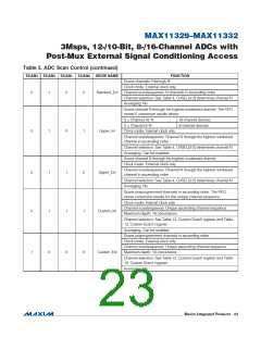
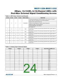
Table 3. ADC Scan Control
SCAN3 SCAN2 SCAN1 SCAN0
MODE NAME
FUNCTION
Continue to operate in the previously selected mode. Ignore data
on bits [10:0]. This feature is provided so that DIN can be held low
when no changes are required in the ADC Mode Control register.
Bits [6:3, 1] can be still written without changing the scan mode
properties.
0
0
0
0
0
0
0
1
Null
The next channel to be selected is identified in each SPI frame. The
conversion results are sent out in the next frame.
Clock mode: External clock only
Manual
Channel scan/sequence: Single channel per frame
Channel selection: See Table 4, CHSEL[3:0]
Averaging: No
Scans channel N repeatedly. The FIFO stores 4, 8, 12, or 16
conversion results for channel N.
Clock mode: Internal clock only
0
0
0
0
1
1
0
1
Repeat
Channel scan/sequence: Single channel per frame
Channel selection: See Table 4, CHSEL[3:0]
Averaging: Can be enabled
Scans channels 0 through N. The FIFO stores N conversion results.
Clock mode: Internal clock
Standard_Int
Channel scan/sequence: N channels in ascending order
Channel selection: See Table 4, CHSEL[3:0] determines channel N
Averaging: Can be enabled
���������������������������������������������������������������� Maxim Integrated Products 22

 MAXIM [ MAXIM INTEGRATED PRODUCTS ]