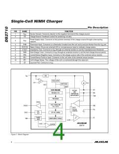
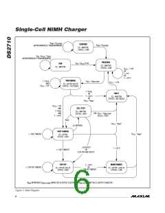
Single-Cell NiMH Charger
charge current to the battery. The load-current return
path should be to charger ground to reduce the likeli-
hood of false termination or impedance-test errors.
Charging with load applied is not recommended.
Charge-Current Regulation
The DS2710 regulates charge current by maintaining a
constant average voltage across an external sense
resistor connected between the VN1 and VN0 pins.
VN1 and VN0 drive an internal comparator in the
DS2710 to switch the CS output ON and OFF to drive a
regulating pnp bipolar or a pMOS transistor. Hysteresis
on the comparator input provides noise rejection. The
DS2710 regulates the charge current during FAST-
CHARGE to maintain a voltage drop across the sense
resistor as follows:
Temperature Monitoring
Accurate temperature sensing is needed to detect tem-
perature FAULT conditions. Connecting an external
DS2710
10kΩ NTC thermistor between THM and V
and a
SS
10kΩ bias resistor between V
and THM allows the
DD
DS2710 to sense temperature. To accurately monitor
the cell, the thermistor should make physical contact
either to the cell or cell tabs. Table 1 shows several rec-
ommended 10kΩ thermistors.
V
= V
- 0.5 x V
= 0.113V (typ)
HYS-COMP
SENSE
IREF
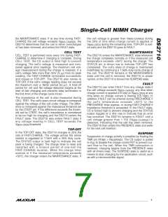
Figure 3 shows the sense resistor voltage and CS pin
voltage of the regulating circuit during normal operation.
MIN, MAX Temperature Compare
The voltage thresholds of the THM input (V
THM-MAX
,
THM-MIN
Charging with Load Applied
NiMH cells have a low, but finite, impedance. If load
current is flowing out of the battery, an internal voltage
drop appears at the battery terminals. This can interfere
with the CTEST and -ΔV detection. If the load current is
variable, early termination is more likely than if the load
current is constant. If the load’s ground is connected to
the negative terminal of the cell (VN0), load current
flows through the current-sense resistor, resulting in less
V
) are set to allow charging to start if the ther-
mistor temperature is between 0°C and +45°C when
using the recommended 10kΩ bias resistor and 10kΩ
thermistor circuit. If precharging is in progress and the
voltage on THM reaches V
, precharging
THM-STOP
stops and a FAULT condition is generated. If the volt-
age on THM reaches V during FAST-
THM-STOP
CHARGE or TOP-OFF, charging stops and the DS2710
enters the MAINTENANCE state. FAST-CHARGE and
Table 1. THM Thresholds
TEMPERATURE (°C)
THERMISTOR
Fenwal
197-103LAG-A01,
173-103LAF-301
THM THRESHOLD
RATIO OF V
RESISTANCE
CBIAS
Semitec 103AT-2
(kꢀ)
MIN
MAX
STOP
0.73
0.33
0.29
27.04
4.925
4.085
0
+4
+45
+50
+42
+47
NOT DRAWN TO SCALE
DIVIDER OUTPUT
V
OH1
0.75
0.70
0.65
0.60
0.55
0.50
0.45
0.40
0.35
0.30
V
CS
V
V
OL1
IREF
V
V
V
(DC)
SENSE
SENSE
0
10
20
30
40
50
- V
HYS-COMP
IREF
TEMPERATURE (°C)
TIME
Figure 3. Ideal Comparator Input and Charge Control Output
Waveforms
Figure 4. Ratio of THM Pin to V
Pin Over Temperature
DD
8
_______________________________________________________________________________________

 MAXIM [ MAXIM INTEGRATED PRODUCTS ]