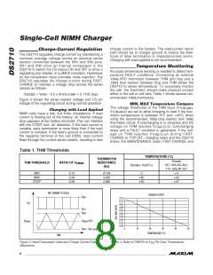
Single-Cell NiMH Charger
Timeout Selection
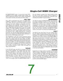
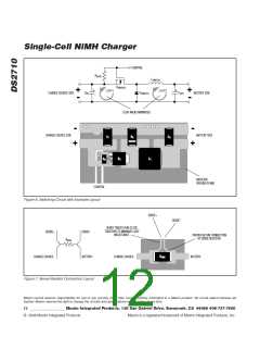
Application Circuit
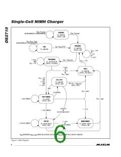
FAST-CHARGE state normally operates until -ΔV termi-
nation. In the event that termination does not occur cor-
rectly, a safety timeout is required. This timeout is set
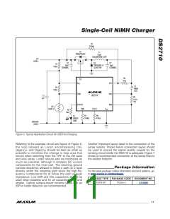
Figure 5 shows a typical DS2710 application circuit for
charging a NiMH cell from a USB port or other 5V
charge source capable of supplying 0.5A. Q1, L1, C2,
and D2 form a switching buck-regulator circuit con-
trolled by the CS pin of the DS2710. Current is regulat-
ed through the current-sense resistor, R9, by switching
Q1 on and off as the sense resistor voltage ramps up
and down toward the preset sense voltage thresholds.
The 0.100Ω sense resistor along with the DC ground-
by an external resistor on the TMR pin to V and pro-
SS
vides secondary protection against significant over-
charging. The value of the TMR resistor should be
chosen so that the timeout is greater than the FAST-
CHARGE time expected in the application, but not so
much greater that its protection is compromised. If the
timer expires during FAST-CHARGE, the timer count is
reset and charging proceeds to the TOP-OFF charge
state. The TMR resistor also sets the timed charge
duration of TOP-OFF state. The TOP-OFF timeout peri-
od is fixed at half the FAST-CHARGE timeout period.
When the timer expires in TOP-OFF, the DS2710 enters
the MAINTENANCE state.
DS2710
referenced sense threshold level of V
- 1/2 V
HYS-
IREF
sets the average charge current in the example
COMP
to 1.13A. The sense resistor should have a proper
power rating for the chosen charge current.
The TMR resistor is set to 100kΩ for a timeout of 2.5hr.
This is appropriate for cells with a capacity of approxi-
mately 2200mAh when charged with the 1.13A charge
current. The CTEST resistor is set to 47kΩ for an imped-
ance-test threshold of approximately 0.150Ω when
charging at 1.13A. Additionally, R6 protects the VP1 pin
from any stress applied to the exposed tabs of a loose
NiMH cell; R3 creates a weak pullup to offset the leak-
age through D2, which might otherwise cause a false
cell detection; and R1/C1 creates a bypass filter on the
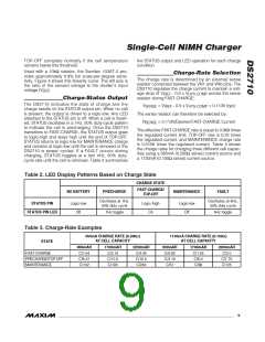
Resistors can be selected to support FAST-CHARGE
timeout periods of 0.5hr to 5hr and TOP-OFF timeout
periods of 0.25hr to 2.5hr. The programmed FAST-
CHARGE time approximately follows the equation:
t(minutes) = 1.5 x R
(Ω)/1000
TMR
Impedance-Test Threshold
Selection
The DS2710 tests the cell impedance every 31s while
in FAST-CHARGE state. Impedance is measured by
comparing the cell voltage during normal charging to
the cell voltage with no charge current (CS output held
high). The resulting voltage difference is compared
against the threshold set by an external resistor from
V
DD
pin of the IC.
The value of L1 in Figure 5 represents a moderate
switching speed of ~ 200kHz for FAST-CHARGE state.
L1 can be adjusted to fit specific application goals as
long as the associated change in switching speed
does not exceed the circuit’s ability to maintain proper
regulation of the sense-resistor voltage. All capacitors
should be ceramic surface-mount types of good quality
where possible. The 10µF capacitor can be of any type
that meets the application requirements. All resistors
not previously mentioned are standard surface-mount
types.
CTEST to V . The detection threshold can be set from
SS
32mV to 400mV. The following formula approximates
the setting for the detection threshold:
V
= 8000/R
(Value in Volts)
TEST
CTEST
Application PCB Layout
Since the charge rate is controlled by the external
sense resistor (R ) between VN1 and VN0, the test
threshold can be expressed as impedance as follows:
Proper layout rules must be followed to ensure a suc-
cessful application circuit. For all modes of operation,
currents in excess of 1A can flow through the charge
and discharge paths (USB charging is specification lim-
ited to 500mA). All these paths should be properly sized
to handle the worst-case current flow, whether from
charging or from powering the load with the battery.
SENSE
Impedance Threshold =
( 8000/R
)/( 0.113/R
SENSE CTEST
) =
SENSE
CTEST
70796 x ( R
/R
)
For example, an application charging at 1.13A (R
SENSE
Switch-mode operation presents challenges with fast
voltage and current transients. Proper switch-mode
buck power-supply layout should always be observed.
= 0.100Ω) would use a 47kΩ resistor on the CTEST pin
to set the impedance threshold to 0.150Ω.
10 ______________________________________________________________________________________

 MAXIM [ MAXIM INTEGRATED PRODUCTS ]