Single-Cell NiMH Charger
DS2710
V
V
rises above V
, or when V
drops below
DD
DD
UVLO
Detailed Description
- V
. If undervoltage lockout is active,
UVLO
UHYS
Charge Algorithm Overview
The DS2710 controls switch-mode topology charging of
a single NiMH cell from a voltage-regulated charge
source. The IC is reset in one of two ways: with the
application of power to the DS2710 or after exiting
SUSPEND state. Once one of these conditions occurs,
the DS2710 enters the PRESENCE state and waits for a
cell to be inserted before starting a charge cycle.
charging is prevented, the state machine is forced to
the POR state, and all charge timers are reset.
PRESENCE
The DS2710 enters the PRESENCE state whenever the
TMR pin is not floating and V
> V
, indicating
UVLO
DD
that the charge source is present. The DS2710 remains
in the PRESENCE state until a cell is inserted into the
circuit, causing the voltage of VP1 - VN1 to fall below
Once a cell is detected, the DS2710 enters PRECHARGE
state and begins qualification to prevent fast charging
of deeply depleted cells or charging under extreme
temperature conditions. Precharging is performed at a
reduced rate until the cell reaches 1V. The algorithm
then proceeds to the FAST-CHARGE state, which
includes cell tests to avoid accidental charging of alka-
line cells or NiMH cells that are worn out or damaged.
Fast charging continues as long as all the cell qualifica-
tion criteria are met. Fast charging terminates by the
-ΔV (negative delta voltage) method. The TOP-OFF
charge phase follows to completely charge the cell.
After the TOP-OFF charge timer expires, the DS2710
enters the MAINTENANCE state to indefinitely keep the
cell at a full state of charge. Maximum voltage, temper-
ature, and charge-time monitoring during all charge
phases act as secondary or safety termination methods
to provide additional protection from overcharge. Any
error condition occurring during charge forces the
DS2710 into the FAULT state and charging terminates.
Charging can be halted at any time by floating the TMR
pin, which forces the DS2710 into SUSPEND state.
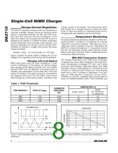
1.65V (V
) and the cell temperature is inside a
MAX-OPEN
valid charging range between 0°C and +45°C
(T and T when used with recommend-
THM-MIN
THM-MAX
ed thermistor and resistor values). If both these condi-
tions are met, the DS2710 enters PRECHARGE. If a cell
is inserted but the temperature is outside the valid
charging range, the DS2710 remains in the PRESENCE
state until the cell temperature falls within the valid
charging range.
PRECHARGE
The DS2710 enters the PRECHARGE state when a valid
cell voltage is detected and the cell temperature as
measured by the DS2710 thermistor circuit is within the
valid charging range. The DS2710 precharges the cell
by regulating the voltage drop across the sense resis-
tor to 113mV with a 25% duty cycle. The STATUS out-
put toggles at 1Hz to indicate the cell is being
precharged. Precharging lasts until the measured cell
voltage exceeds 1.0V (V
DS2710 enters the FAST-CHARGE state. If the cell volt-
age does not exceed V
the cell temperature exceeds +50°C (T
any time during PRECHARGE, the DS2710 enters the
FAULT state. If at any time during PRECHARGE the cell
voltage exceeds 1.75V (V
), at which time the
LOW
within 30min (t
) or if
THM-STOP
LOW
PCHG
) at
Once a charge is complete either normally or by
FAULT, the DS2710 remains in the final state (MAINTE-
NANCE or FAULT) until the cell is removed, the IC is
power cycled, or the IC is forced into SUSPEND state.
Afterwards, the DS2710 returns to PRESENCE state
and the charge cycle begins again.
), the DS2710
MAX-CHARGE
determines that the cell has been removed and enters
the FAULT state.
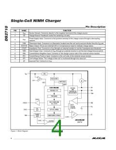
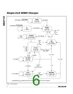
An internal oscillator provides the main clock source
used to generate timing signals for chip operation. The
PRECHARGE timer, hold-off timers, and timing for CS
operation and cell testing are derived from this time
base. If the internal clock should ever fail, a watchdog-
detection circuit halts charging. The watchdog-safety
circuit and charge timer set by the TMR pin are derived
from oscillators other than the main clock source. Figure
1 is the DS2710 block diagram and Figure 2 is the state
diagram.
FAST-CHARGE
In the FAST-CHARGE state, the DS2710 regulates the
average voltage across the sense resistor to 113mV.
The STATUS output is held high to indicate the cell
pack is being charged. During FAST-CHARGE, the
DS2710 performs a cell test every 31s. The CELL TEST
state is responsible for determining when charge is
complete. As secondary overcharge protection, the
DS2710 terminates FAST-CHARGE and enters TOP-
OFF based on a time delay set by the external resistor
on the TMR pin. This resistor value can set the sec-
ondary charge termination delay to anywhere from
30min up to 5hr. If the cell temperature exceeds +50°C
at any time during FAST-CHARGE, the DS2710 enters
POWER-ON RESET (POR)
The UVLO circuit serves as a power-up and brownout
detector by monitoring V
to prevent charging until
DD
_______________________________________________________________________________________
5

 MAXIM [ MAXIM INTEGRATED PRODUCTS ]