DS2413: 1-Wire Dual Channel Addressable Switch
1-Wire SIGNALING
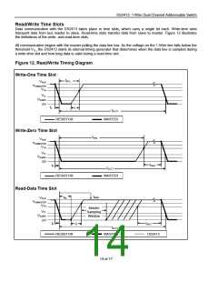
The DS2413 requires strict protocols to ensure data integrity. The protocol consists of four types of signaling on
one line: Reset Sequence with Reset Pulse and Presence Pulse, Write-Zero, Write-One, and Read-Data. Except
for the Presence pulse, the bus master initiates all falling edges. The DS2413 can communicate at two different
speeds, standard speed, and Overdrive Speed. If not explicitly set into the Overdrive mode, the DS2413
communicates at standard speed. While in Overdrive Mode the fast timing applies to all waveforms.
To get from idle to active, the voltage on the 1-Wire line needs to fall from VPUP below the threshold VTL. To get
from active to idle, the voltage needs to rise from VILMAX past the threshold VTH. The time it takes for the voltage to
make this rise is seen in Figure 11 as 'ꢁ' and its duration depends on the pullup resistor (RPUP) used and the
capacitance of the 1-Wire network attached. The voltage VILMAX is relevant for the DS2413 when determining a
logical level, not triggering any events.
Figure 11 shows the initialization sequence required to begin any communication with the DS2413. A Reset Pulse
followed by a Presence Pulse indicates the DS2413 is ready to receive data, given the correct ROM and PIO
Function command. If the bus master uses slew-rate control on the falling edge, it must pull down the line for tRSTL
+ tF to compensate for the edge. A tRSTL duration of 480µs or longer exits the Overdrive Mode, returning the device
to standard speed. If the DS2413 is in Overdrive Mode and tRSTL is no longer than 80µs, the device remains in
Overdrive Mode. If the device is in Overdrive Mode and tRSTL is between 80µs and 480µs, the device will reset, but
the communication speed is undetermined.
Figure 11. Initialization Procedure: Reset and Presence Pulse
MASTER TX “RESET PULSE” MASTER RX “PRESENCE PULSE”
tMSP
ꢀ
VPUP
VIHMASTER
VTH
VTL
VILMAX
0V
tF
tRSTL
tPDL
tRSTH
tPDH
MASTER
tREC
RESISTOR
DS2413
After the bus master has released the line it goes into receive mode. Now the 1-Wire bus is pulled to VPUP through
the pullup resistor, or in case of a DS2482-x00 or DS2480B driver, by active circuitry. When the threshold VTH is
crossed, the DS2413 waits for tPDH and then transmits a Presence Pulse by pulling the line low for tPDL. To detect a
presence pulse, the master must test the logical state of the 1-Wire line at tMSP
.
The tRSTH window must be at least the sum of tPDHMAX, tPDLMAX, and tRECMIN. Immediately after tRSTH is expired, the
DS2413 is ready for data communication. In a mixed population network, tRSTH should be extended to minimum
480µs at standard speed and 48µs at Overdrive speed to accommodate other 1-Wire devices.
13 of 17

 MAXIM [ MAXIM INTEGRATED PRODUCTS ]