71M6543F/H and 71M6543G/GH Data Sheet
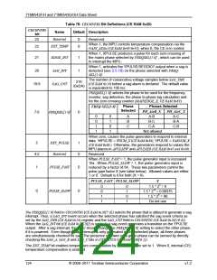
The CE pulse generator can be controlled by either the MPU (external) or CE (internal) variables. Control is by
the MPU if the EXT_PULSE bit = 1 (CE RAM 0x20[5]). In this case, the MPU controls the pulse rate (external
pulse generation) by placing values into APULSEW and APULSER (CE RAM 0x45 and 0x49). By setting
EXT_PULSE = 0, the CE controls the pulse rate based on WSUM_X (CE RAM 0x84) and VARSUM_X (CE
RAM 0x88).
The 71M6543 Demo Code creep function halts both internal and external pulse generation.
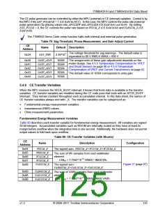
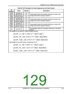
Table 79: Sag Threshold, Phase Measurement, and Gain Adjust Control
CE
Name
Default Description
Address
The voltage threshold for sag warnings. The default value is
equivalent to 80 V RMS if VMAX = 600 V.
2.39*107
SAG_THR
0x24
GAIN_ADJ0
GAIN_ADJ1
GAIN_ADJ2
GAIN_ADJ3
GAIN_ADJ4
0x40
0x41
0x42
0x43
0x44
16384
16384
16384
16384
16384
The assignments of these gain adjustments depends on the
meter design. See 4.5.5 Temperature Compensation for VREF
and Shunt Sensors on page 90 or 4.5.6 Temperature
Compensation of VREF and Current Transformers on page 92.
The default value of 16384 corresponds to unity gain.
5.4.8 CE Transfer Variables
When the MPU receives the XFER_BUSY interrupt, it knows that fresh data is available in the transfer
variables. CE transfer variables are modified during the CE code pass that ends with an XFER_BUSY
interrupt. They remain constant throughout each accumulation interval. In this data sheet, the names of
CE transfer variables always end with _X. The transfer variables can be categorized as:
•
•
•
Fundamental energy measurement variables
Instantaneous (RMS) values
Other measurement parameters
Fundamental Energy Measurement Variables
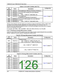
Table 80 describes each transfer variable for fundamental energy measurement. All variables are signed
32-bit integers. Accumulated variables such as WSUM are internally scaled so they have at least 2x
margin before overflow when the integration time is one second. Additionally, the hardware does not permit
output values to fold back upon overflow.
Table 80: CE Transfer Variables (with Shunts)
CE
Name
Description
Configuration
Address
WSUM_X
W0SUM_X
W1SUM_X
W2SUM_X
VARSUM_X
The signed sum: W0SUM_X+W1SUM_X+W2SUM_X.
0x84
0x85
The sum of Wh samples from each wattmeter
element.
0x86
LSBW = 7.7562*10-13 VMAX * IMAX Wh.
0x87
Figure 31 (page 87)
0x88
The signed sum:
VAR0SUM_X+VAR1SUM_X+VAR2SUM_X.
VAR0SUM_X
VAR1SUM_X
VAR2SUM_X
0x89
0x8A
0x8B
The sum of VARh samples from each wattmeter
element.
LSBW = 7.7562*10-13 VMAX * IMAX VARh.
v1.2
© 2008–2011 Teridian Semiconductor Corporation
125

 MAXIM [ MAXIM INTEGRATED PRODUCTS ]