LTC4413
U
OPERATIO
occurs.Duringovercurrentoperation,thepowerconsump-
tion of the LTC4413 will be large, and is likely to cause an
overtemperatureconditionastheinternaldietemperature
exceeds the thermal shutdown temperature.
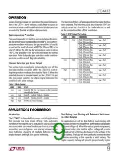
ThefunctionoftheSTATpindependsonthemodethathas
been selected. The following table describes the STAT pin
output current as a function of the mode selected, as well
as the conduction state of the two diodes.
Table 2. STAT Output Pin Funtion
Overtemperature Protection
ENB1
ENB2
CONDITIONS
STAT
The overtemperature condition is detected when the inter-
nal die temperature increases beyond 150°C. An overtem-
perature condition will cause the gate amplifiers (A and B)
as well as the two P-channel MOSFETs (PA and PB) to be
shut off. When the internal die temperature cools to below
140°C, the amplifiers will turn on and revert to normal
operation. Note that prolonged operation under overtem-
perature conditions will degrade reliability.
Low
Low
Diode A Forward Bias,
Diode B Forward Bias
I
I
I
I
I
I
I
I
I
= 0µA
= 0µA
= 9µA
= 9µA
= 0µA
= 9µA
= 0µA
= 9µA
= 9µA
SNK
SNK
SNK
SNK
SNK
SNK
SNK
SNK
SNK
Diode A Forward Bias,
Diode B Reverse Bias
Diode A Reverse Bias,
Diode B Forward Bias
Diode A Reverse Bias,
Diode B Reverse Bias
Low
High
High
High
Low
High
Diode A Forward Bias,
Diode B Disabled
Channel Selection and Status Output
Diode A Reverse Bias,
Diode B Disabled
Two active-high control pins independently turn off the
two ideal diodes contained within the LTC4413, control-
lingtheoperationmodeasdescribedbyTable1. Whenthe
selected channel is reverse biased, or the LTC4413 is put
into low power standby, the status signal indicates this
condition with a low voltage.
Diode A Disabled,
Diode B Forward Bias
Diode A Disabled
Diode B Reverse Bias
Diode A Disabled,
Diode B Disabled
Table 1. Mode Control
ENB1
ENB2
STATE
Low
Low
Diode OR (NB: The Two Outputs are Not Connected
Internal to the Device)
Low
High
High
High
Low
High
Diode A = Enabled, Diode B = Disabled
Diode A = Disabled, Diode B = Enabled
All 0ff (Low Power Standby)
W U U
U
APPLICATIO S I FOR ATIO
Introduction
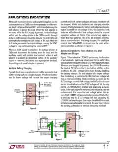
Dual Battery Load Sharing with Automatic Switchover
to a Wall Adapter
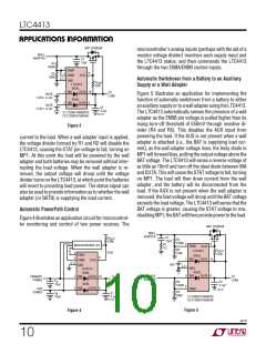
The LTC4413 is intended for power control applications
that include low loss diode ORing, fully automatic
switchoverfromaprimarytoanauxiliarysourceofpower,
microcontroller controlled switchover from a primary to
an auxiliary source of power, load sharing between two or
more batteries, charging of multiple batteries from a
single charger and high side power switching.
An application circuit for dual battery load sharing with
automaticswitchoverofloadfrombatteriestoawalladapter
is shown in Figure 3. When the wall adapter is not present,
whichever battery that has the higher voltage will provide
theloadcurrentuntilithasdischargedtothevoltageofthe
otherbattery.Theloadwillthenbesharedbetweenthetwo
batteries according to the capacity of each battery. The
higher capacity battery will provide proportionally higher
4413f
9

 Linear [ Linear ]