LTC4413
W U U
APPLICATIO S I FOR ATIO
U
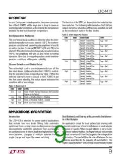
current until both battery voltages are equal, then both will
be charged. While both batteries are charging simulta-
neously, the higher capacity battery will get proportionally
higher current from the charger. For Li-Ion batteries, both
batteries will achieve the float voltage minus the forward
regulation voltage of 20mV. This concept can apply to
more than two batteries. The STAT pin provides informa-
tion as to when battery 1 is being charged. For intelligent
control, the ENBA/ENBB pin inputs can be used with a
microcontroller as shown in Figure 4.
If the AUX is present when a wall adapter is applied, as the
resistivedividertoENBBrisesthroughtheturn-offthresh-
old,theSTATpinwillfallandMP1willconductallowingthe
wall adapter to power the load. When the wall adapter is
removed while the AUX supply is present, the load voltage
willfalluntilthevoltagedividerattheENBBpinfallsthrough
its turn-on threshold. Once this occurs, the LTC4413 will
automaticallyconnecttheAUXsupplytotheloadwhenthe
AUXvoltageexceedstheoutputvoltage, causingtheSTAT
voltage to rise and disabling the external PFET.
When an AUX supply is attached, the voltage divider at
ENBA will disconnect the battery from the load, and the
auxiliary supply will provide load current, unless a wall
adapter is present as described earlier. If the auxiliary
supply is removed, the battery may again power the load,
depending on if a wall adapter is present.
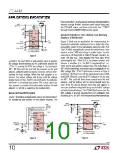
Automatic Switchover from a Battery to a Wall
Adapter and Charger
Figure 7 illustrates the LTC4413 performing the function
of automatically switching a load over from a battery to a
walladapterwhilecontrollinganLTC4059batterycharger.
When no wall adapter is present, the LTC4413 connects
the load at OUTA from the Li-Ion battery at INA. In this
condition, the STAT voltage will be high, thereby disabling
the battery charger. If a wall adapter of a higher voltage
than the battery is connected to INB, the load voltage will
rise as the second ideal diode conducts. As soon as the
OUTAvoltageexceedsINAvoltage, theBATwillbediscon-
nected from the load and the STAT voltage will fall, turning
on the LTC4059 battery charger and beginning a charge
cycle. If the wall adapter is removed, the voltage at INB will
collapse until it is below the load voltage. When this oc-
curs, theLTC4413willautomaticallyreconnectthebattery
to the load and the STAT voltage will rise, disabling the
LTC4059 battery charger. One major benefit of this circuit
isthatwhenawalladapterispresent,theusermayremove
the battery and replace it without disrupting the load.
Multiple Battery Charging
Figure6illustratesanapplicationcircuitforautomaticdual
battery charging from a single charger. Whichever battery
has the lower voltage will receive the larger charging
STAT IS HIGH
WHEN BAT1
470k
LTC4413
STAT
9
IS CHARGING
IDEAL
BATTERY
CHARGER
INPUT
1
5
INA
OUTA 10
LOAD1
LOAD2
BAT1
BAT2
IDEAL
INB
OUTB
6
2
4
ENBA
ENBB
GND
3,11
4413 F06
Figure 6
LTC4413
9
STAT
R1
560k
LTC4059
IDEAL
INA
1
OUTA 10
V
BAT
CC
2
4
ENB
PROG
ENBA
ENBB
GND
1-CELL
Li-Ion
R2
100k
3,11
Li CC GND
IDEAL
INB OUTB
5
6
WALL
ADAPTER
TO LOAD
C1: C0805C106K8PAC
C2: C1206C475K8PAC
C1
10µF
C2
4.7µF
4413 F07
Figure 7
4413f
Information furnished by Linear Technology Corporation is believed to be accurate and reliable.
However, no responsibility is assumed for its use. Linear Technology Corporation makes no represen-
tationthattheinterconnectionofitscircuitsasdescribedhereinwillnotinfringeonexistingpatentrights.
11

 Linear [ Linear ]