LTC4413
W U U
U
APPLICATIO S I FOR ATIO
MP1 FDR8508
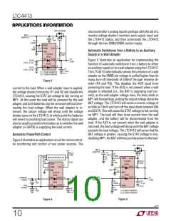
microcontroller’s analog inputs (perhaps with the aid of a
resistor voltage divider) monitors each supply input and
the LTC4413 status, and then commands the LTC4413
through the two ENBA/ENBB control inputs.
WALL
ADAPTER
C1
10µF
R1
1000k
2
4
ENBA
ENBB
GND
9
R2
200k
STAT
3,11
Automatic Switchover from a Battery to an Auxiliary
Supply or a Wall Adapter
R
STAT
LTC4413
IDEAL
OUTA 10
470k
1
5
INA
INB
TO
LOAD
BATA
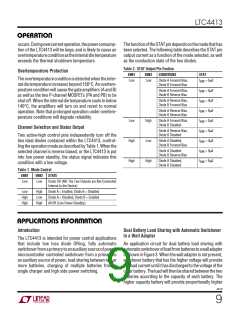
Figure 5 illustrates an application for implementing the
function of automatic switchover from a battery to either
an auxiliary supply or to a wall adapter using the LTC4413.
The LTC4413 automatically senses the presence of a wall
adapter as the ENBB pin voltage is pulled higher than its
rising turn-off threshold of 550mV through resistive di-
vider (R4 and R5). This disables the AUX input from
powering the load. If the AUX is not present when a wall
adapter is attached (i.e., the BAT is supplying load cur-
rent), as the wall adapter voltage rises, the body diode in
MP1willforwardbias,pullingtheoutputvoltageabovethe
BAT voltage. The LTC4413 will sense a reverse voltage of
as little as 10mV and turn off the ideal diode between INA
and OUTA. This will cause the STAT voltage to fall, turning
on MP1. The load will then draw current from the wall
adapter, and the battery will be disconnected from the
load. If the AUX is not present when the wall adapter is
removed, the load voltage will droop until the BAT voltage
exceeds the load voltage. The LTC4413 will sense that the
BAT voltage is greater, causing the STAT voltage to rise,
disablingMP1;theBATwillthenprovidepowertotheload.
1-CELL Li-Ion
IDEAL
OUTB
6
BATB
C2
4.7µF
1-CELL Li-Ion
C1:C1206C106K8PAC
C2:C1206C475K8PAC
4413 F03
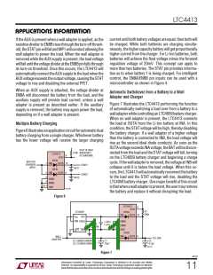
Figure 3
current to the load. When a wall adapter input is applied,
the voltage divider formed by R1 and R2 will disable the
LTC4413, causing the STAT pin voltage to fall, turning on
MP1. At this point the load will be powered by the wall
adapter and both batteries may be removed without inter-
rupting the load voltage. When the wall adapter is re-
moved, the output voltage will droop until the voltage
divider turns on the LTC4413, at which point the batteries
will revert to providing load power. The status signal can
also be used to provide information as to whether the wall
adapter (or BATB) is supplying the load current.
Automatic PowerPath Control
Figure 4 illustrates an application circuit for microcontrol-
ler monitoring and control of two power sources. The
MP1 FDR8508
WALL
ADAPTER
C1
R
STAT
R2
10µF
470k
1000k
9
4
1
R1
1Ω
MICROCONTROLLER
ENBB
LTC4413
IDEAL
OUTA 10
STAT
R3
100k
R
STAT
STAT
2
470k
ENBA
9
4
INA
ENBB
STAT
3,11
BAT
GND
3,11
5
GND
LTC4413
IDEAL
OUTA 10
IDEAL
OUTB
INB
6
AUX
ADAPTER
1
5
INA
PRIMARY
POWER
TO
LOAD
TO
LOAD
C
A
R4
C2
4.7µF
IDEAL
OUTB
10µF
1000k
2
INB
6
ENBA
AUX
POWER
4413 F05
R5
500k
C
10µF
C1
4.7µF
B
C1:C0805C106K8PAC
C2:C1206C475K8PAC
4413 F04
Figure 5
Figure 4
4413f
10

 Linear [ Linear ]