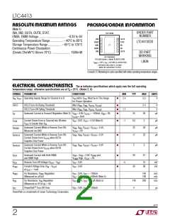
LTC4413
U
U
U
PI FU CTIO S
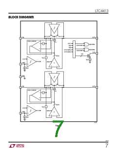
INA (Pin 1): Primary Ideal Diode Anode and Positive
Power Supply. Bypass INA with a ceramic capacitor of at
least 1µF. 1Ω snub resistors in series with a capacitor and
higher valued capacitances are recommended when large
inductances are in series with this input. This pin can be
grounded when not used.
OUTB(Pin6):SecondaryIdealDiodeCathodeandOutput.
BypassOUTBwithahigh(1mΩ min)ESRceramiccapaci-
tor of at least 4.7µF. This pin must be left floating when not
in use.
NC (Pin 7): No Internal Connection.
NC (Pin 8): No Internal Connection.
ENBA (Pin 2): Enable Low for Diode A. Weak (3µA) pull-
down. Pull this pin high to shut down this power path. Tie
to GND to enable. Refer to Table 1 for mode control
functionality. This pin can be left floating, weak pull-down
internal to the LTC4413.
STAT(Pin9):StatusConditionIndicator.Weak(9µA)pull-
down current output. When terminated, STAT = High
indicates diode conducting.
ThefunctionoftheSTATpindependsonthemodethathas
been selected. Table 2 describes the STAT pin output
current as a function of the mode selected as well as the
conductionstateofthetwodiodes.Thispincanalsobeleft
floating or grounded.
GND(Pins3, 11):PowerandSignalGroundfortheIC.The
Exposed Pad of the package, Pin 11, must be soldered to
PCB ground to provide both electrical contact to ground
and good thermal contact to the PCB.
OUTA (Pin 10): Primary Ideal Diode Cathode and Output.
BypassOUTAwithahigh(1mΩ min)ESRceramiccapaci-
tor of at least 4.7µF. This pin must be left floating when not
in use.
ENBB (Pin 4): Enable Low for Diode B. Weak (3µA) pull-
down. Pull this pin high to shut down this power path. Tie
to GND to enable. Refer to Table 1 for mode control
functionality. This pin can be left floating, weak pull-down
internal to the LTC4413.
INB (Pin 5): Secondary Ideal Diode Anode and Positive
Power Supply. Bypass INB with a ceramic capacitor of at
least 1µF. 1Ω snub resistors in series with a capacitor and
higher valued capacitances are recommended when large
inductances are in series with this input. This pin can be
grounded when not used.
4413f
6

 Linear [ Linear ]