LTC3649
OPERATION
If current monitoring is needed but current limiting is not,
The general idea behind this setup is that once the induc-
tor current rises, the current out of the IMON pin will rise
proportionally. As a result, the ISET voltage will increase,
thus increasing the regulated output voltage. This rise of
simplypickanR
resistorsmallenoughsuchthatV
IMON
IMON
will never approach 2V. A 10k resistor along with a 10nF
capacitor is typically a good RC pair to use in this case.
V
offsets the voltage drop across the cable, R
,
OUT
CABLE
If current limiting is useful for the application, it is im-
portant to carefully pick the value of the capacitor from
thus keeping V
constant.
POL
IMON to GND, C
. If C
is picked to be too large,
R
should be sized to account for the amount of cable
SET2
IMON
IMON
then the switching regulator will be slow to react to a
large output transients, and the average inductor current
will rise above the programmed level until the loop can
resistance:
R
SET2
= 40000 • R
CABLE
Furthermore, in order to regulate V
voltage:
at the desired
react. If C
is picked to be too small, then the loop can
POL
IMON
become unstable. Typically, an RC time constant that is
at least 10 times slower than the switching frequency is
a good place to start.
(R
+ R ) • 50µA = V
SET2 POL(DESIRED)
SET1
C
is still required if soft-start is desired for the ap-
SET1
plication, and C
10
1.59
is required to filter out the AC ripple
SET2
CIMON •RIMON
≥
=
2π • fSW fSW
noise of the inductor current. Once again, typically C
SET2
and R
should be sized to have a RC time constant 10
SET2
times slower than the switching frequency.
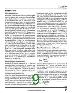
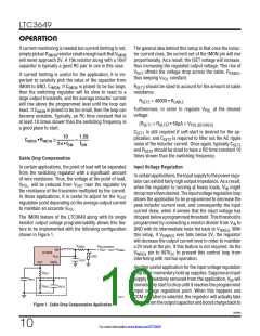
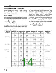
Cable Drop Compensation
In certain applications, the point of load will be separated
from the switching regulator with a significant amount
of wire resistance. Thus, the voltage at the point of load,
Input Voltage Regulation
Incertainapplications, theinputsupplytothepowerregu-
lator can exhibit fairly high output impedance. As a result,
when the regulator is running at heavy loads, V might
V
, will be reduced from V
near the regulator by
POL
OUT
IN
the resistance of the trace/wire multiplied by the current.
droopmorethandesired.Theinputvoltageregulationloop
allows the application to be programmed to decrease the
peak inductor current level, and consequently the input
current draw, when it senses that the input voltage has
droppedbelowaprogrammedthreshold.Thisthresholdis
In those applications, it is useful to adjust for the V
OUT
regulation point depending on the average output current
to maintain an accurate V
.
POL
The IMON feature of the LTC3649 along with its single
resistor output voltage programmability allows this fea-
ture to be implemented with the following configuration
shown in Figure 1.
programmed by connecting a resistor divider from V to
IN
. With
GND with its intermediate node fed back to V
INREG
this setup, if V
ever falls below 2V, the regulator
VINREG
will decrease the output current level in order to maintain
a 2V level at the pin. If this feature is not required, tie the
R
V
CABLE
POL(DESIRED)
OUT OUT CABLE
= V
– I
• R
SW
OUT
LTC3649
V
pin to INTV to prevent this control loop from
INREG
CC
V
LOAD
interfering with normal operation.
C
OUT
ISET
IMON
Another useful application for the input voltage regulation
loop is for momentary hold up supplies. Suppose an input
R
SET1
SET2
C
SET1
supply is suddenly removed from the application, V will
IN
immediately start to drop until it reaches the programmed
input voltage regulation point. When this happens and
CCM operation is selected, the regulator will actually take
chargefromtheoutputcapacitorandboostchargebackto
R
C
SET2
3649 F01
Figure 1. Cable Drop Compensation Application
3649fb
10
For more information www.linear.com/LTC3649

 Linear [ Linear ]