LTC3633A/LTC3633A-1
APPLICATIONS INFORMATION
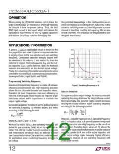
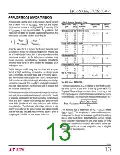
A reasonable starting point is to choose a ripple current
Table 1. Inductor Selection Table
INDUCTANCE DCR
MAX
CURRENT
(A)
DIMENSIONS
(mm)
HEIGHT
(mm)
that is about 40% of I
. Note that the largest
OUT(MAX)
(μH) (mΩ)
ripple current occurs at the highest V . Exceeding 60%
IN
of I
is not recommended. To guarantee that
OUT(MAX)
Würth Electronik WE-HC 744312 Series
ripple current does not exceed a specified maximum, the
inductance should be chosen according to:
0.25
0.47
0.72
1.0
2.5
3.4
18
16
12
11
9
7 × 7.7
3.8
7.5
9.5
10.5
⎛
⎞⎛
⎞
VOUT
f • ΔIL(MAX)
VOUT
V
IN(MAX)
1.5
⎜
⎜
⎟⎜
⎟⎜
⎟
⎟
L =
1–
Vishay IHLP-2020BZ-01 Series
⎝
⎠⎝
⎠
0.22
0.33
0.47
0.68
1
5.2
8.2
8.8
12.4
20
15
12
5.2 × 5.5
2
Once the value for L is known, the type of inductor must
be selected. Actual core loss is independent of core size
for a fixed inductor value, but is very dependent on the
inductance selected. As the inductance increases, core
losses decrease. Unfortunately, increased inductance
requires more turns of wire, leading to increased DCR
and copper loss.
11.5
10
7
Toko FDV0620 Series
0.20
0.47
1.0
4.5
8.3
18.3
12.4
9.0
5.7
7 × 7.7
6 × 8.9
2.0
5.0
3.2
Coilcraft D01813H Series
0.33
0.56
1.2
4
10
17
10
7.7
5.3
Ferrite designs exhibit very low core loss and are pre-
ferred at high switching frequencies, so design goals
can concentrate on copper loss and preventing satura-
tion. Ferrite core material saturates “hard”, which means
that inductance collapses abruptly when the peak design
current is exceeded. This results in an abrupt increase in
inductor ripple current, so it is important to ensure that
the core will not saturate.
TDK RLF7030 Series
1.0
1.5
8.8
9.6
6.4
6.1
6.9 × 7.3
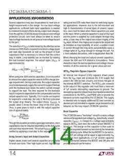
C and C
Selection
IN
OUT
The input capacitance, C , is needed to filter the trapezoi-
IN
dal wave current at the drain of the top power MOSFET.
To prevent large voltage transients from occurring, a low
ESRinputcapacitorsizedforthemaximumRMScurrentis
recommended. The maximum RMS current is given by:
Differentcorematerialsandshapeswillchangethesize/cur-
rent and price/current relationship of an inductor. Toroid
or shielded pot cores in ferrite or permalloy materials are
small and don’t radiate much energy, but generally cost
more than powdered iron core inductors with similar
characteristics. The choice of which style inductor to use
mainly depends on the price versus size requirements
and any radiated field/EMI requirements. Table 1 gives a
sampling of available surface mount inductors.
VOUT V − V
(
)
IN
OUT
I
RMS =IOUT(MAX)
V
IN
This formula has a maximum at V = 2V , where
IN
OUT
I
≅ I /2. This simple worst case condition is com-
RMS
OUT
monlyusedfordesignbecauseevensignificantdeviations
do not offer much relief. Note that ripple current ratings
from capacitor manufacturers are often based on only
2000 hours of life which makes it advisable to further de-
rate the capacitor, or choose a capacitor rated at a higher
temperature than required.
3633a1f
13

 Linear [ Linear ]