LTC3633A/LTC3633A-1
APPLICATIONS INFORMATION
for this purpose and usually incorporates current limiting,
short-circuit protection, and soft starting.
The voltage at the TRACKSS pin may be driven from an
external source, or alternatively, the user may leverage
the internal 1.4μA pull-up current source to implement
a soft-start function by connecting an external capacitor
MODE/SYNC Operation
(C ) from the TRACKSS pin to ground. The relationship
SS
The MODE/SYNC pin is a multipurpose pin allowing both
mode selection and operating frequency synchronization.
between output rise time and TRACKSS capacitance is
given by:
Floating this pin or connecting it to INTV enables Burst
CC
Modeoperationforsuperiorefficiencyatlowloadcurrents
attheexpenseofslightlyhigheroutputvoltageripple.When
the MODE/SYNC pin is tied to ground, forced continuous
modeoperationisselected,creatingthelowestfixedoutput
ripple at the expense of light load efficiency.
t
= 430000Ω • C
SS
SS
A default internal soft-start ramp forces a minimum soft-
start time of 400μs by overriding the TRACKSS pin input
during this time period. Hence, capacitance values less
than approximately 1000pF will not significantly affect
soft-start behavior.
The LTC3633A will detect the presence of the external
clock signal on the MODE/SYNC pin and synchronize the
internal oscillator to the phase and frequency of the in-
coming clock. The presence of an external clock will place
both regulators into forced continuous mode operation.
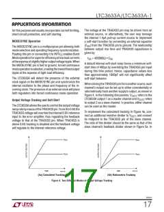
WhendrivingtheTRACKSSpinfromanothersource, each
channel’s output can be set up to either coincidentally or
ratiometrically track another supply’s output, as shown in
Figure 4. In the following discussions, V
LTC3633A output 1 as a master channel and V
to output 2 as a slave channel. In practice, either channel
can be used as the master.
refers to the
OUT2
OUT1
refers
Output Voltage Tracking and Soft-Start
TheLTC3633Aallowstheusertocontroltheoutputvoltage
rampratebymeansoftheTRACKSSpin.From0to0.6V,the
TRACKSS voltage will override the internal 0.6V reference
input to the error amplifier, thus regulating the feedback
voltage to that of the TRACKSS pin. When TRACKSS is
above 0.6V, tracking is disabled and the feedback voltage
will regulate to the internal reference voltage.
To implement the coincident tracking in Figure 4a, con-
nect an additional resistive divider to V
its midpoint to the TRACKSS pin of the slave channel.
The ratio of this divider should be the same as that of the
slave channel’s feedback divider shown in Figure 5a. In
and connect
OUT1
V
V
OUT1
OUT1
V
V
OUT2
OUT2
3633a F04b
TIME
TIME
3633a F04a
(4a) Coincident Tracking
(4b) Ratiometric Tracking
Figure 4. Two Different Modes of Output Voltage Tracking
3633a1f
17

 Linear [ Linear ]