LTC3101
APPLICATIONS INFORMATION
provides a small sampling of inductors that are well suited
to many LTC3101 buck-boost converter applications. All
inductor specifications are listed at an inductance value
of 4.7μH for comparison purposes but other values within
these inductor families are generally well suited to this ap-
plication. Within each family (i.e., at a fixed size), the DC
resistance generally increases and the maximum current
generally decreases with increased inductance.
capacitance in ꢀF, L is the inductance in ꢀH, and I
the output current in Amps.
is
LOAD
V – V
V
(
)
1
IN
OUT OUT
ΔVP-P(BUCK)
=
•
8 •L •COUT • f2
V
IN
ILOAD
VOUT – V
IN
(
)
ΔVP-P(BOOST)
=
COUT • VOUT • f
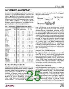
Table 5. Representative Buck-Boost Surface Mount Inductors
Given that the output current is discontinuous in boost
mode, therippleinthismodewillgenerallybemuchlarger
than the magnitude of the ripple in buck mode. In addi-
tion to controlling the ripple magnitude, the value of the
output capacitor also affects the location of the resonant
frequency in the open-loop converter transfer function.
If the output capacitor is too small, the bandwidth of the
converter will extend high enough to degrade the phase
margin.Topreventthisfromhappening,itisrecommended
that a minimum value of 10ꢀF be used for the buck-boost
output capacitor. If the required buck-boost load current
is greater than 400mA, it is recommended that the output
capacitor be increased to 22μF to improve output voltage
ripple and loop stability.
VALUE DCR
MAX DC
SIZE (mm)
W × L × H
PART NUMBER
(ꢀH)
(mΩ) CURRENT (A)
Coilcraft
LPS4018
LPS4012
ME3220
MSS5121
4.7
4.7
4.7
4.7
125
175
190
95
1.9
1.8
4.0 × 4.0 × 1.8
4.0 × 4.0 × 1.2
3.2 × 2.5 × 2.0
5.4 × 5.4 × 2.1
1.5
1.66
Cooper-Bussmann
SD12
SD14
4.7
4.5
118
94
1.29
1.74
5.2 × 5.2 × 1.2
5.2 × 5.2 × 1.4
Panasonic
ELL6PG
ELL5PS
4.7
4.7
58
61
1.5
1.5
6.0 × 6.0 × 2.0
5.0 × 5.0 × 1.85
Sumida
CDRH3D18
CDRH4D15/S
CDRH4D22/HP
4.7
4.7
4.7
86
103
66
1.35
1.4
2.2
4.0 × 4.0 × 2.0
4.7 × 4.7 × 1.7
5.0 × 5.0 × 2.4
Taiyo-Yuden
NR6020T
NP04SZB
Buck-Boost Input Capacitor Selection
4.7
4.7
58
75
2.0
1.8
6.0 × 6.0 × 2.0
5.0 × 5.0 × 2.0
Thesupplycurrenttothebuck-boostconverterisprovided
bytheUSB2andBAT2pins. Inaddition, thesepinsprovide
power to the internal circuitry of the LTC3101. It is recom-
mended that a low ESR ceramic capacitor with a value of
at least 10ꢀF be located as close to each of these pins as
possible. In addition, the return trace from each pin to the
ground plane should be made as short as possible.
TOKO
DE2815C
DP418C
DE4514C
4.7
4.7
4.7
100
50
1.3
1.50
1.9
3.0 × 2.8 × 1.5
4.2 × 4.2 × 1.8
4.7 × 4.9 × 1.4
100
Wurth
744042004
7447785004
7447745056
4.7
4.7
4.7
82
78
57
1.65
2.20
2.40
4.8 × 4.8 × 1.8
5.9 × 6.2 × 3.3
5.2 × 5.8 × 2.0
Buck-Boost Output Capacitor Selection
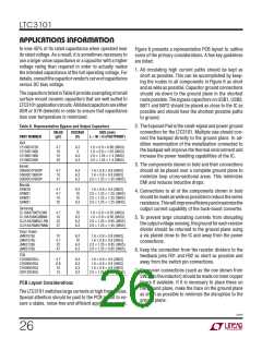
Capacitor Vendor Information
A low ESR output capacitor should be utilized at the buck-
boost converter output in order to minimize output volt-
age ripple. Multilayer ceramic capacitors are an excellent
choice as they have low ESR and are available in small
footprints. The capacitor should be chosen large enough
to reduce the output voltage ripple to acceptable levels.
Neglecting the capacitor ESR and ESL, the peak-to-peak
output voltage ripple can be calculated by the following
Both the input bypass capacitors and DC/DC converter
outputcapacitorsusedwiththeLTC3101mustbelowESR
and designed to handle the large AC currents generated
by switching converters. This is important to maintain
proper functioning of the IC and to reduce output ripple.
Many modern low voltage ceramic capacitors experience
significant loss in capacitance from their rated value
with increased DC bias voltages. For example, it is not
uncommon for a small surface mount ceramic capacitor
formulas, where f is the frequency in MHz, C
is the
OUT
3101f
25

 Linear [ Linear ]