LTC3101
APPLICATIONS INFORMATION
If a substantially larger output capacitor is utilized, the
bandwidth of the loop will be reduced. In such cases, the
feedforward capacitor can be increased in value in order
to lower the zero frequency and improve the transient
response.
buck-boost inductor must have a saturation current rat-
ing that is greater than the worst-case average inductor
current plus half the ripple current. The peak-to-peak
inductor current ripple will be larger in buck and boost
mode then in the buck-boost region. The peak-to-peak
inductor current ripple for each mode can be calculated
from the following formulas, where f is the frequency in
MHz and L is the inductance in ꢀH:
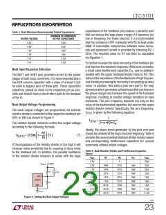
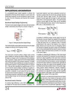
Buck-Boost Output Voltage Programming
Thebuck-boostoutputvoltageissetviaanexternalresistor
divider connected to the FB3 pin as shown in Figure 5.
⎛
⎞
⎟
VOUT V – VOUT
IN
ΔIL(P-P)(BUCK)
=
⎜
f •L
V
5.25 ≥ V
≥ 1.5V
⎝
⎠
OUT3
IN
R2
⎛
⎜
⎝
⎞
VOUT – V
V
f •L
IN
IN
ΔIL(P-P)(BOOST)
=
FB3
⎟
VOUT
⎠
LTC3101
GND
R1
In addition to affecting output current ripple, the size of
the inductor can also impact the stability of the feedback
loop. In boost mode, the converter transfer function has
a right half plane zero at a frequency that is inversely
proportional to the value of the inductor. As a result, a
large inductor can move this zero to a frequency that is
low enough to degrade the phase margin of the feedback
loop. It is recommended that the inductor value be chosen
less than 10ꢀH if the buck-boost converter is to be used
in the boost region.
3101 F05
Figure 5. Setting the Buck-Boost Output Voltage
Theresistordividervaluesdeterminethebuck-boostoutput
voltage according to the following formula:
⎛
⎞
R2
R1
VOUT3 = 0.599 1+
V
( )
(2)
⎜
⎝
⎟
⎠
In addition to affecting the efficiency of the buck-boost
converter, the inductor DC resistance can also impact the
maximum output capability of the buck-boost converter
at low input voltage. In buck mode, the buck-boost output
current is limited only by the inductor current reaching the
current limit value. However, in boost mode, especially at
large step-up ratios, the output current capability can also
be limited by the total resistive losses in the power stage.
These include switch resistances, inductor resistance,
and PCB trace resistance. Use of an inductor with high
DC resistance can degrade the output current capability
from that shown in the graph in the Typical Performance
Characteristics section of this data sheet.
The buck-boost converter utilizes voltage mode control
and in addition to setting the output voltage, the value of
R2 plays an integral role in the dynamics of the feedback
loop. In general, a larger value for R2 will increase stability
and reduce the speed of the transient response. A smaller
value of R2 will reduce stability but increase the speed of
the transient response. A good starting point is to choose
R2 = 1M and then calculate the required value of R1 to
set the desired output voltage according to Equation 2.
If a large output capacitor is used, the bandwidth of the
converter is reduced. In such cases R2 can be reduced
to improve the transient response. If a large inductor or
smalloutputcapacitorisutilizedtheloopwillbelessstable
and the phase margin can be improved by increasing the
value of R2.
Differentinductorcorematerialsandstyleshaveanimpact
on the size and price of an inductor at any given current
rating. Shielded construction is generally preferred as it
minimizes the chances of interference with other circuitry.
Thechoiceofinductorstyledependsupontheprice,sizing,
Buck-Boost Inductor Selection
To achieve high efficiency, a low ESR inductor should
be utilized for the buck-boost converter. In addition, the
and EMI requirements of a particular application. Table 5
3101f
24

 Linear [ Linear ]