LTC2309
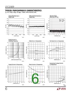
APPLICATIONS INFORMATION
4 Differential
8 Single-Ended
1st Conversion
2nd Conversion
CH0
CH1
+ (
)
)
CH0
CH1
CH2
CH3
CH4
CH5
CH6
CH7
+
+
+
+
+
+
+
+
–
{
{
{
{
(
+
–
+
–
+
–
CH2
CH3
–
+
CH2
CH3
{
{
{
{
+ (
)
)
CH2
CH3
–
(
+
–
CH4
CH5
+
+
CH4
CH5
+ (
)
)
CH4
CH5
–
(
+
–
COM
(UNUSED)
COM (
)
–
CH6
CH7
+ (
)
)
–
(
2328 F01b
+
COM (
)
–
–
Figure 1b. Changing the MUX Assignments “On the Fly”
Combinations of Differential
and Single-Ended
CH0
+
Unipolar Mode
Bipolar Mode
{
CH1
–
CH2
CH3
–
{
COM
COM
+
+
REFCOMP/2
+
+
+
+
CH4
CH5
CH6
CH7
–
2328 F02
Figure 2. Driving COM in Unipolar and Bipolar Modes
COM (
)
–
2309 F01a
mode, the analog inputs draw only a small leakage cur-
rent. If the source impedance of the driving circuit is
low, the ADC inputs can be driven directly. Otherwise,
more acquisition time should be allowed for a source
with higher impedance.
Figure 1a. Example of MUX Configurations
Table 1. Channel Configuration
S/D O/S S1 S0
0
1
2
3
4
5
6
+
–
+
7
–
+
COM
0
0
0
0
0
0
0
0
1
1
1
1
1
1
1
1
0
0
0
0
1
1
1
1
0
0
0
0
1
1
1
1
0
0
1
1
0
0
1
1
0
0
1
1
0
0
1
1
0
1
0
1
0
1
0
1
0
1
0
1
0
1
0
1
+
–
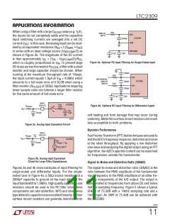
Input Filtering
+
–
The noise and distortion of the input amplifier and
other circuitry must be considered since they will add
to the ADC noise and distortion. Therefore, noisy input
circuitry should be filtered prior to the analog inputs to
minimize noise. A simple 1-pole RC filter is sufficient
for many applications.
+
–
–
+
+
–
+
+
–
+
+
The analog inputs of the LTC2309 can be modeled as
–
–
–
–
–
–
–
–
a 55pF capacitor (C ) in series with a 100ꢀ resistor
IN
(R ) as shown in Figure 3a. C gets switched to the
ON
IN
selectedinputonceduringeachconversion.Largefilter
RC time constants will slow the settling of the inputs.
It is important that the overall RC time constants be
short enough to allow the analog inputs to completely
settle to 12-bit resolution within the acquisition time
+
+
+
(t ) if DC accuracy is important.
ACQ
+
2309f
10

 Linear [ Linear ]