LTC1698
W U U
U
APPLICATIO S I FOR ATIO
The core must be sized to provide sufficient window area
for the amount of wire and insulation needed. The best
performance is achieved by making each winding a single
layer evenly distributed across the width of the bobbin.
Multiple layers may be used to increase the copper area.
Interleaving the primary and secondary windings will
decrease the leakage inductance.
Power Transformer Selection
The forward transformer provides DC isolation and deliv-
ers energy from the primary to the secondary. Unlike the
flybacktopology, thetransformerintheforwardconverter
is not an energy storage device. As such, ungapped ferrite
material is typically used. Select a power material rated
with low loss at the switching frequency. Many core
manufacturershaveselectionguidesandapplicationnotes
for transformer design. A brief overview of the more
important design considerations is presented here.
In a single-ended forward converter, much of the energy
stored in the leakage inductance is dissipated in the
primary-side MOSFET during turn-off. It is good design
practice to sandwich the secondary winding between two
primary windings.
For operating frequencies greater than 100kHz, the flux
in the core is usually limited by core loss, not saturation.
It is important to review both criteria when selecting the
transformer. The AC operating flux density for core loss is
given by:
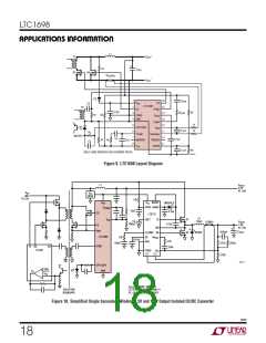
For the 2-transistor forward converter shown in Figure 1,
energy stored in the leakage inductance is returned to the
input by diodes D1 and D2. With this topology, additional
insulation for higher isolation can be used without signifi-
cant penalty.
V •DC •108
2•NP •Ae • fSW
IN
BAC
=
For a more detailed discussion on transformer core and
winding losses, see Application Note AN19.
where:
Inductor Selection
BAC is the AC operating flux density (gauss)
DC is the operating duty cycle
The output inductor in a typical LTC1698 circuit is chosen
for inductance value and saturation current rating. The
output inductor in a forward converter operates the same
as in a buck regulator. The inductance sets the ripple
current, which is commonly chosen to be 40% of the full
load current. Ripple current is set by:
Ae is the effective cross sectional core area (cm2)
fSW is the switching frequency
To prevent core saturation during a transient condition,
the peak flux density is:
VOUT • tOFF(MAX)
IRIPPLE
where:
tOFF(MAX)
=
V
IN(MAX) •DC (MAX)•108
L
BPK
=
NP •Ae • fSW
The minimum secondary turns count is:
1– DC (MIN)
(
)
=
VOUT + VD
VIN(MIN)•DC(MAX)
fSW
NS(MIN) = NP •
and DC(MIN) is calculated based on the maximum input
voltage.
where:
VOUT is the secondary output voltage
NP VOUT
VD is the voltage drop across the rectifier in the secondary
VIN(MIN) is the minimum input voltage
DC(MIN) =
•
NS
V
IN(MAX)
DC(MAX) is the maximum duty cycle
1698f
16

 Linear [ Linear ]