LTC1698
W U U
APPLICATIO S I FOR ATIO
U
Once the value of the inductor has been determined, an
inductor with sufficient DC current rating is selected. Core
saturationmustbeavoidedunderalloperatingconditions.
Under start-up conditions, the converter sees a short
circuit while charging the output capacitor. If the inductor
saturates, the peak current will dramatically increase. The
current will be limited only by the primary controller
minimum on time and the circuit impedances.
Fast load current transitions at the output will appear as a
voltage across the ESR of the output capacitor until the
feedback loop can change the inductor current to match
the new load current value. As an example: at 3.3V out, a
10A load step with a 0.01Ω ESR output capacitor would
experience a 100mV step at the output, a 3% output
change. In surface mount applications, multiple capaci-
tors may have to be placed in parallel to meet the ESR
requirement.
Highefficiencyconvertersgenerallycannotaffordthecore
loss found in low cost iron powder cores, forcing the use
of more expensive ferrite, molypermalloy, or Kool Mµ®
cores. As inductance increases, core loss goes down.
Increased inductance requires more turns of wire so
copper losses will increase. The optimum inductor will
have equal core and copper loss.
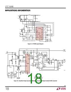
PC Board Layout Checklist
When laying out the printed circuit board, the following
checklist should be used to ensure proper operation of the
LTC1698. These items are also illustrated graphically in
Figure 9. Check the following for your layout:
1. Keep the power circuit and the signal circuit segre-
gated. Place the power circuit, shown in bold, so that
the two MOSFET drain connections are made directly at
thetransformer.ThetwoMOSFETsourcesshouldbeas
close together as possible.
Ferritedesignshaveverylowcorelossesandarepreferred
at higher switching frequencies. Therefore, design goals
concentrate on minimizing copper loss and preventing
saturation. Kool Mµ is a very good, low-loss powder
material with a “soft” saturation characteristic.
Molypermalloy is more efficient at higher switching fre-
quencies, but is also more expensive. Surface mount
designs are available from many manufacturers using all
of these materials.
2. Connect PGND directly to the sense resistor with as
short a path as possible. The MOSFET gate drive return
currents flow through this connection.
3. Connect the 4.7µF ceramic capacitor directly between
V
DD andPGND. ThissuppliestheFGandCGdriversand
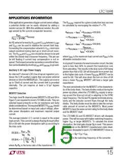
Output Capacitor Selection
must supply the gate drive current.
The output capacitor selection is primarily determined by
the effective series resistance (ESR) to minimize voltage
ripple. In a forward converter application, the inductor
current is constantly flowing to the output capacitor,
therefore, the ripple current at the output capacitor is
small. Theoutputripplevoltageisapproximatelygivenby:
4. Bypass the VAUX supply with a 0.1µF ceramic capacitor
returned to GND.
5. Place all signal components in close proximity to their
associated LTC1698 pins. Return all signal component
grounds directly to the GND pin. One common connec-
tion can be made to VOUT+ from R2, R5 and CCILM
.
1
VRIPPLE ≈ IRIPPLE • ESR +
6. Make the connection between GND and PGND right at
the LTC1698 pins.
8• fSW •COUT
The output ripple is highest at maximum input voltage
since IRIPPLE increases with input voltage. Typically, once
the ESR requirement for COUT has been satisfied the
capacitance is adequate for filtering and has the required
RMS current rating.
7. UseaKelvin-senseconnectionfromtheISNSandISNSGND
pins to the secondary-side current-limit resistor
RSECSEN
.
Kool Mµ is a registered trademark of Magnetics, Inc.
1698f
17

 Linear [ Linear ]