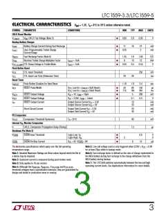
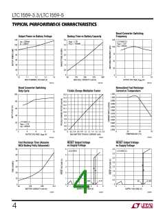
LTC1559-3.3/LTC1559-5
U
W
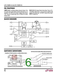
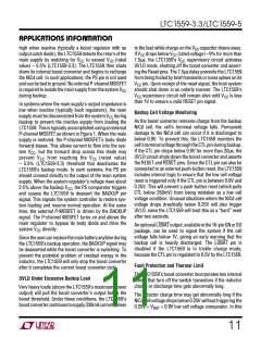
SWITCHING WAVEFORMS
Cold Power Boot-Up Description
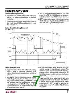
3. The LTC1559’s internal bandgap wakes up. QEXT turns
on and VCC = PS. The LTC1559’s internal boost con-
verter does not turn on as RESET remains asserted.
1. System regulator starts to ramp up the output (PS)
once the VBAT voltage increases beyond the minimum
input value.
4. RESETisassertedforafurther200msafterVCC reaches
–5.5% of its rated VCC value for the LTC1559-3.3 and
–6% of its rated VCC value for the LTC1559-5.
2. VCC startstoincreaseoncePSishighenoughtoturnon
QEXT’s body diode. RESET is asserted when VCC is less
than or equal to 1V.
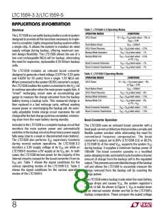
Backup Mode (Main Battery Discharged)—
LTC1559-3.3
1V
1.2V
0.9V
V
NiCd
BOOST CONVERTER OUTPUT
–7%
–5.5%
–7%
–7%
V
CC
t
t
f
r
BACKUP
INDUCTOR
CURRENT
t
r
t
r
“1”
RESET
t
r
“1”
LOBAT
(1)
(2)
(3)
(4)
1559 SW03
Backup Mode Description
3. Recovery from Backup Mode. While the boost con-
verter is running, the main battery is restored. This
causes the system regulator to increase PS above VCC.
When PS > VCC or VCC > VCC(rated value) –5.5%, the
BACKUPpindeassertsandtheboostconverterfinishes
its last cycle.
1. Trigger into Backup Mode. Main battery fails and VCC
drops 7% below the rated value. The backup pin is
asserted after a tr delay time and the boost converter is
turned on.
2. Backup Mode. The LTC1559’s boost converter charges
and discharges the inductor with 165mA peak current.
If VCC doesn’t increase above VCC(rated value) – 7%
(due to a heavy load), the boost converter increases
peak charging current to 330mA. If VCC rises above
VCC(rated value) – 7%, the boost converter stops and
the backup pin remains asserted.
4. Trigger into UVLO. During backup, the 1.2V NiCd cell is
dischargedanditsterminalvoltagefalls.TheLOBATpin
is asserted to give an early warning if the cell voltage
drops below 1V. RESET is asserted when the cell
voltage drops below 0.9V and the LTC1559 enters
UVLO mode.
7

 Linear [ Linear ]