LTC1559-3.3/LTC1559-5
U
W U U
APPLICATIONS INFORMATION
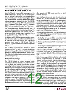
Table 1. LTC1559-3.3 Operating Modes
OPERATING MODES
Overview
CONDITIONS
TheLTC1559isaversatilebackupbatterycontrolsystem
designed to provide all the functions necessary to imple-
mentacomplete, highlyintegratedbackupsystemwithin
a single chip. It allows the system to maintain its rated
supply voltage during backup, offering maximum sys-
tem design flexibility. The LTC1559 allows the use of a
low cost rechargeable NiCd cell for backup, eliminating
the need for expensive, replaceable 4.5V lithium backup
cells.
UVLO Reset
1V < V < V (rated value) – 9% or
CC CC
V
< 0.9V
BAT
Push-Button Reset
UVLO Reset Recovery
Backup Mode Activation
Backup Mode Exit
V
< 250mV
CTL
V
> V (rated value) – 5.5%
CC
CC
CC
V
< V (rated value) – 7%
CC
CC
V
> V (rated value) – 5.5%
CC
or PS > V
CC
Boost Converter Activation
Boost Converter Deactivation
V
< V (rated value) – 7%
CC
CC
CC
V
> V (rated value) – 7%
CC
The LTC1559 includes an onboard boost converter
designed to generate a fixed voltage (3.07V for 3.3V parts
and 4.625V for 5V parts) from a single 1.2V NiCd cell.
When connected to the system DC/DC converter’s output,
the LTC1559 enables the system connected to the VCC rail
to continue operation when the main power supply fails. A
“smart” recharging circuit uses an accumulating gas
gauge to measure the charge extracted from the backup
battery during a backup cycle. This measured charge is
then replaced in a fast recharge cycle, without wasting
excess power or overcharging the backup cell. An exter-
nally adjustable trickle charge circuit maintains the cell
chargeafterthefastchargecyclehascompleted, minimiz-
ing drain from the main battery during standby.
Table 2. LTC1559-5 Operating Modes
OPERATING MODES
CONDITIONS
UVLO Reset
1V < V < V (rated value) – 9%
CC CC
or V
< 0.9V
BAT
Push-Button Reset
UVLO Reset Recovery
Backup Mode Activation
Backup Mode Exit
V
< 250mV
CTL
V
> V (rated value) – 6%
CC
CC
V
< V (rated value) – 7.5%
CC
CC
V
> V (rated value) – 6%
CC
CC
or PS > V
CC
Boost Converter Activation
Boost Converter Deactivation
V
< V (rated value) – 7.5%
CC
CC
CC
V
> V (rated value) – 7.5%
CC
Boost Converter Operation
Included in the LTC1559 is a complete backup circuit that
monitors the main system power and automatically
switchesinthebackupcircuitastheprimarypowersupply
falls away (due to a weak or disconnected main battery).
The LTC1559 also performs VCC supervisory functions
during normal system operations. An LTC1559-3.3
monitors a 3.3V supply voltage at its VCC pin while an
LTC1559-5 monitors a 5V supply at its VCC pin. In both
cases, the LTC1559 derives power for the majority of the
internal circuitry (except for the boost converter) from its
VCC pin. Table 1 shows the signal conditions for the
various operating modes of the LTC1559-3.3. Table 2
shows the signal conditions for the various operating
modes of the LTC1559-5.
The LTC1559 uses an onboard boost converter with a
fixed peak current architecture that provides a simple and
flexible system solution while eliminating the need for
conventional frequency compensation. The boost
converter’s output, set to 93% (LTC1559-3.3) or 92.5%
(LTC1559-5) of the rated VCC, supports the system VCC
during backup. It supplies a minimum backup power of
100mW. The boost converter operates in a modified
pulse-skippingmode;eachswitchcycletransfersaknown
amount of charge from the backup cell to the regulated
output.Thispreventsuncontrolleddischargeofthebackup
cell and allows the LTC1559 to accurately measure the
charge removed from the backup cell by counting the
charge pulses.
The LTC1559 enters backup mode when the main battery
voltage drops and causes VCC, the system regulator’s
output, to fall. As shown in Figure 1, VCC is scaled down
by an internal resistor divider and fed to the LTC1559’s
backup comparators. These compare the scaled voltage
8

 Linear [ Linear ]