LTC1559-3.3/LTC1559-5
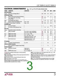
ELECTRICAL CHARACTERISTICS VBAT = 1.2V, TA = 0°C to 70°C unless otherwise noted.
SYMBOL PARAMETER
UVLO Reset Monitor
CONDITIONS
MIN
TYP
0.9
16
MAX
UNITS
V
V
UVLO Trip Voltage (Note 5)
●
0.85
0.95
V
LOBAT2
BAT
Backup Battery Charger
I
I
Battery Charge Current During Fast Recharge
●
●
11
21
2
mA
mA
CHGF
CHGT
User-Programmable Trickle Charge
Current Range
0.05
Q
Q
Fast Recharge Factor (Note 6)
1.35
8
1.6
10
1.85
12
C/C
A/A
V
RECH
Nominal Trickle Charge Multiplier Factor
CTL Clamp Voltage in Trickle Mode
I
I
= 1mA
= 1mA
●
●
TRK
CHGT
CHGT
V
0.45
0.5
0.55
CTL(CLAMP)
Push-Button Reset
V
CTL Input Threshold
250
mV
ms
CTL
CTL
t
CTL Input Low Time (Debounce Time)
20
26
Reset Timer
t
t
Push-Button Duration for Hard Reset
RESET Pulse Width
1.10
1.8
3.4
sec
HRESET
RST
V
CTL
V
CTL
Low for <t
Low for >t
(Soft Reset)
(Hard Reset)
●
●
50
115
80
185
150
345
µs
ms
HRESET
HRESET
V
V
RESET Output Voltage
RESET Output Voltage
RESET Output Current
V
V
= 1V, I = 10µA
SINK
●
●
5
200
0.4
mV
V
RST1
RST
CC
CC
= 4.25V, I
= 1.6mA
0.1
SINK
I
Output Source Current V = 3.3V
Output Source Current V = 5V
10
20
mA
mA
SC
CC
CC
Short-Circuit Current
Output Sink Current V = 3.3V
20
40
mA
mA
CC
Output Sink Current V = 5V
CC
PS Comparator
Comparator Threshold Hysteresis
Internal V Monitor Comparator
V
T = 25°C
A
90
mV
HYST
CC
tr
UVLO, Comparator Propagation Delay (Rising)
7.5
µs
Shutdown Pin (Note 3)
V
SHDN Input Threshold
Logic Low, V
●
●
0.8
15
V
V
SHDN
IL
IH
Logic High, V
2
I
SHDN Pin Bias Current
V
CC
= 5V, V
= 0V
●
8
µA
SHDN
SHDN
The
●
denotes specifications which apply over the full operating
Note 5: Low cell voltage reset is only triggered when 0.25V < V < 0.9V
for at least 20µs while in backup mode.
CTL
temperature range.
Note 1: Absolute Maximum Ratings are those values beyond which the life of
a device may be impaired.
Note 2: Quiescent current is measured during push-button reset.
Note 3: Only applies to 16-pin version.
Note 6: Fast recharge factor is defined as the ratio of charge replenished to
the NiCd battery during fast recharge to the charge withdrawn from the
NiCd battery during backup.
Note 7: The LTC1559 switches automatically between the low and high
operating current levels. See Applications Information for more details.
Note 4: Although the V
, V
, V
and V
BAK(ON) BAK(OFF) UVLO(ON) UVLO(OFF)
threshold voltages have a specification tolerance, they are guaranteed by
design and tested in production never to overlap.
3

 Linear [ Linear ]