LT5581
APPLICATIONS INFORMATION
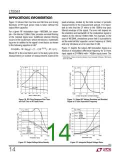
the output pin, to form an RC lowpass filter. The internal
of 3, using a 0.047μF external filter capacitor. The aver-
age power in the preamble section is –10dBm, while the
burst section has a 3dB lower average power. With the
capacitor, therippleinthepreamblesectionisabout0.5dB
peak-to-peak. The modulation used was OFDM (WiMAX
802.16-2004) MMDS band, 1.5MHz BW, with 256 size FFT
300ꢀ resistor in series with the output pin enables filter-
ing of the output signal with just the addition of C
.
LOAD
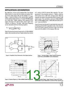
Figure 7 shows the effect of the external filter capacitor
on the residual ripple level for a 4-carrier WCDMA signal
at 2.14GHz with –10dBm. Adding a 10nF capacitor to the
output decreases the peak-to-peak output ripple from
3
and 1 burst at QPSK /4.
135mV to 50mV . The filter –3dB corner frequency
P-P
P-P
Figure9showshowthepeak-to-peakrippledecreaseswith
increasing external filter capacitance value. Also shown is
how the RF pulse response will have longer rise and fall
times with the addition of this lowpass filter cap.
can be calculated with the following equation:
1
fC =
2π CLOAD(300 + RSS)
Figure8showsthetransientresponsefora2.6GHzWiMAX
signal, with preamble and burst ripple reduced by a factor
1.4
1.2
1.25
1.20
T
= 25°C
A
LT5581
INPUT
V
CC
NO CAP
0.01μF
1.0
1.15
40μA
0.8
0.6
0.4
0.2
1.10
1.05
1.00
0.95
V
OUT
300ꢀ
R
SS
V
3
OUT
(FILTERED)
C
LOAD
0
0.90
20 30 40 50 60
TIME (μs)
100
70 80 90
0
10
5581 F07
Figure 6. Simplified Circuit Schematic of the Output Interface
Figure 7. Residual Ripple, Output Transient Response
for RF Pulse with WCDMA 4-Carrier Modulation
9
8
7
6
5
4
3
2
1
1000
100
10
1.4
RIPPLE
RISE
FALL
T
= 25°C
T
= 25°C
A
NO CAP
0.047μF
A
1.2
1.0
0.8
0.6
0.4
0.2
0
1
0
0.01
0.1
1
0.001
0.4 0.6 0.8
1
1.2
2
0
0.2
1.4 1.6 1.8
EXTERNAL CAPACITOR (μF)
TIME (ms)
5581 F09
5581 F08
Figure 8. Residual Ripple for 2.6GHz WiMAX OFDM 802.16-2004
Figure 9. Residual Ripple, Output Transient Times for RF Pulse
with WCDMA 4-Carrier Modulation vs External Filter Capacitor C4
5581f
13

 Linear [ Linear ]