LT1576/LT1576-5
U
W U U
APPLICATIONS INFORMATION
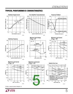
sufficiently low duty cycle if switching frequency were
maintained at 200kHz, so frequency is reduced by about
5:1 when the feedback pin voltage drops below 0.7V (see
FrequencyFoldbackgraph). Thisdoesnotaffectoperation
with normal load conditions; one simply sees a gear shift
in switching frequency during start-up as the output
voltage rises.
Table 1
OUTPUT
VOLTAGE
(V)
R1
% ERROR AT OUTPUT
R2
(NEAREST 1%) DUE TO DISCREET 1%
(kΩ
)
(k
Ω
)
RESISTOR STEPS
–0.50
3
3.3
5
4.99
4.99
4.99
4.99
4.99
4.99
4.99
4.99
7.32
8.66
15.8
19.6
28.0
36.5
44.2
56.2
+0.30
+0.83
6
–0.62
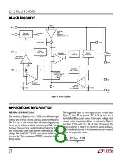
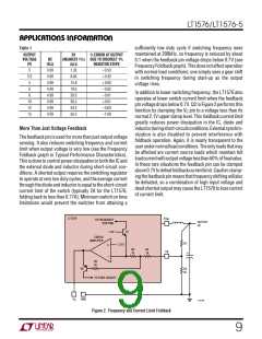
In addition to lower switching frequency, the LT1576 also
operates at lower switch current limit when the feedback
pin voltage drops below 0.7V. Q2 in Figure 2 performs this
function by clamping the VC pin to a voltage less than its
normal 2.1V upper clamp level. This foldback current limit
greatly reduces power dissipation in the IC, diode and
inductorduringshort-circuitconditions.Externalsynchro-
nization is also disabled to prevent interference with
foldback operation. Again, it is nearly transparent to the
userundernormalloadconditions.Theonlyloadsthatmay
be affected are current source loads which maintain full
loadcurrentwithoutputvoltagelessthan50%offinalvalue.
In these rare situations the feedback pin can be clamped
above0.7Vtodefeatfoldbackcurrentlimit.Caution:clamp-
ingthefeedbackpinmeansthatfrequencyshiftingwillalso
be defeated, so a combination of high input voltage and
deadshortedoutputmaycausetheLT1576tolosecontrol
of current limit.
8
–0.01
10
12
15
+0.61
–0.60
– 1.08
More Than Just Voltage Feedback
The feedback pin is used for more than just output voltage
sensing. It also reduces switching frequency and current
limit when output voltage is very low (see the Frequency
Foldback graph in Typical Performance Characteristics).
ThisisdonetocontrolpowerdissipationinboththeICand
the external diode and inductor during short-circuit con-
ditions. A shorted output requires the switching regulator
to operate at very low duty cycles, and the average current
throughthediodeandinductorisequaltotheshort-circuit
current limit of the switch (typically 2A for the LT1576,
folding back to less than 0.77A). Minimum switch on time
limitations would prevent the switcher from attaining a
LT1576
V
SW
TO FREQUENCY
OUTPUT
5V
SHIFTING
1.4V
Q1
ERROR
AMPLIFIER
R1
1.21V
+
–
R3
1k
R4
1k
FB
+
R5
5k
Q2
R2
5k
TO SYNC CIRCUIT
V
C
GND
1576 F02
Figure 2. Frequency and Current Limit Foldback
9

 Linear [ Linear ]