LT1576/LT1576-5
U
W U U
APPLICATIONS INFORMATION
Output Capacitor Ripple Current (RMS):
dI
dt
VRIPPLE = I
ESR + ESL Σ
(
P-P)(
) (
)
0.29 V
V − V
IN OUT
(
OUT)(
)
Example: withVIN =10V,VOUT =5V,L=30µH,ESR=0.1Ω,
IRIPPLE RMS
=
(
)
L f V
ESL = 10nH:
( )( )( )
IN
5 10 − 5
Ceramic Capacitors
( )(
)
I
=
= 0.42A
P-P
−6
3
Higher value, lower cost ceramic capacitors are now
becomingavailableinsmallercasesizes.Thesearetempt-
ing for switching regulator use because of their very low
ESR. Unfortunately, the ESR is so low that it can cause
loop stability problems. Solid tantalum capacitor’s ESR
generatesaloop“zero”at5kHzto50kHzthatisinstrumen-
tal in giving acceptable loop phase margin. Ceramic
capacitors remain capacitive to beyond 300kHz and usu-
allyresonatewiththeirESLbeforeESRbecomeseffective.
They are appropriate for input bypassing because of their
highripplecurrentratingsandtoleranceofturn-onsurges.
10 30• 10
200• 10
( )
dI
dt
10
6
Σ
=
= 0.33• 10
−6
30• 10
−9
6
V
= 0.42A 0.1 + 10• 10
0.33• 10
(
)( )
RIPPLE
= 0.042 + 0.003 = 45mV
P-P
20mV/DIV
VOUT AT
OUT = 1A
I
INDUCTOR
CURRENT
AT IOUT = 1A
200mA/DIV
OUTPUT RIPPLE VOLTAGE
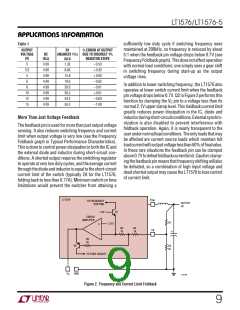
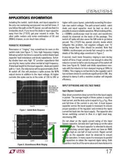
Figure 3 shows a typical output ripple voltage waveform
for the LT1576. Ripple voltage is determined by the high
frequency impedance of the output capacitor, and ripple
current through the inductor. Peak-to-peak ripple current
through the inductor into the output capacitor is:
20mV/DIV
VOUT AT
IOUT = 50mA
INDUCTOR
200mA/DIV
CURRENT
AT IOUT = 50mA
2µs/DIV
1576 F03
Figure 3. LT1576 Ripple Voltage Waveform
V
V − V
IN OUT
(
OUT)(
)
IP-P
=
V
L f
IN)( )( )
(
CATCH DIODE
For high frequency switchers, the sum of ripple current
slew rates may also be relevant and can be calculated
from:
The suggested catch diode (D1) is a 1N5818 Schottky, or
its Motorola equivalent, MBR130. It is rated at 1A average
forward current and 30V reverse voltage. Typical forward
voltage is 0.42V at 1A. The diode conducts current only
during switch off time. Peak reverse voltage is equal to
regulatorinputvoltage.Averageforwardcurrentinnormal
operation can be calculated from:
dI
dt
V
IN
L
Σ
=
Peak-to-peak output ripple voltage is the sum of a triwave
created by peak-to-peak ripple current times ESR, and a
square wave created by parasitic inductance (ESL) and
ripple current slew rate. Capacitive reactance is assumed
to be small compared to ESR or ESL.
IOUT V − V
(
)
IN
OUT
=
V
IN
13

 Linear [ Linear ]