LT1576/LT1576-5
U
W U U
APPLICATIONS INFORMATION
2
Assume that the average inductor current is equal to
load current and decide whether or not the inductor
must withstand continuous fault conditions. If maxi-
mum load current is 0.5A, for instance, a 0.5A inductor
may not survive a continuous 1.5A overload condition.
Dead shorts will actually be more gentle on the induc-
tor because the LT1576 has foldback current limiting.
IOUT(MAX)
=
I
f L V
IN
( ) ( )( )(
)
P
Discontinuous mode
2 V
V − V
(
)(
)
OUT
IN
OUT
Example: with L = 5µH, VOUT = 5V, and VIN(MAX) = 15V,
2
3
−6
1.5 200• 10 5• 10
15
( )
(
)
I
=
= 0.34A
OUT MAX
(
)
2 5 15 − 5
( )(
2. Calculate peak inductor current at full load current to
ensure that the inductor will not saturate. Peak current
can be significantly higher than output current, espe-
cially with smaller inductors and lighter loads, so don’t
omit this step. Powdered iron cores are forgiving
because they saturate softly, whereas ferrite cores
saturate abruptly. Other core materials fall somewhere
in between. The following formula assumes continu-
ous mode of operation, but it errs only slightly on the
high side for discontinuous mode, so it can be used for
all conditions.
)
The main reason for using such a tiny inductor is that it is
physically very small, but keep in mind that peak-to-peak
inductorcurrentwillbeveryhigh. Thiswillincreaseoutput
ripplevoltage.Iftheoutputcapacitorhastobemadelarger
to reduce ripple voltage, the overall circuit could actually
wind up larger.
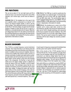
CHOOSING THE INDUCTOR AND OUTPUT CAPACITOR
For most applications the output inductor will fall in the
rangeof15µHto60µH. Lowervaluesarechosentoreduce
physical size of the inductor. Higher values allow more
output current because they reduce peak current seen by
the LT1576 switch, which has a 1.5A limit. Higher values
also reduce output ripple voltage, and reduce core loss.
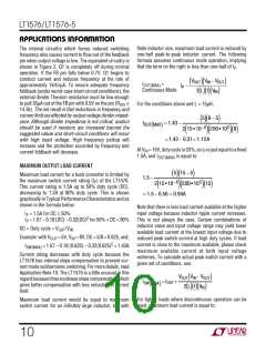
GraphsintheTypicalPerformanceCharacteristicssection
show maximum output load current versus inductor size
andinputvoltage. Asecondgraphshowscorelossversus
inductor size for various core materials.
VOUT V − V
(
)
IN
OUT
IPEAK =IOUT +
2 f L V
( )( )(
)
IN
VIN = Maximum input voltage
f = Switching frequency, 200kHz
3. Decide if the design can tolerate an “open” core geom-
etry like a rod or barrel, with high magnetic field
radiation, orwhetheritneedsaclosedcorelikeatoroid
to prevent EMI problems. One would not want an open
core next to a magnetic storage media, for instance!
Thisisatoughdecisionbecausetherodsorbarrelsare
temptingly cheap and small and there are no helpful
guidelines to calculate when the magnetic field radia-
tion will be a problem.
When choosing an inductor you might have to consider
maximum load current, core and copper losses, allowable
component height, output voltage ripple, EMI, fault cur-
rent in the inductor, saturation, and of course, cost. The
following procedure is suggested as a way of handling
thesesomewhatcomplicatedandconflictingrequirements.
4. Start shopping for an inductor (see representative
surfacemountunitsinTable2)whichmeetstherequire-
mentsofcoreshape,peakcurrent(toavoidsaturation),
average current (to limit heating), and fault current (if
the inductor gets too hot, wire insulation will melt and
cause turn-to-turn shorts). Keep in mind that all good
thingslikehighefficiency,lowprofile,andhightempera-
ture operation will increase cost, sometimes dramati-
cally. Get a quote on the cheapest unit first to calibrate
yourself on price, then ask for what you really want.
1. Choose a value in microhenries from the graphs of
maximumloadcurrentandcoreloss.Choosingasmall
inductor may result in discontinuous mode operation
at lighter loads, but the LT1576 is designed to work
well in either mode. Keep in mind that lower core loss
means higher cost, at least for closed core geometries
like toroids. The core loss graphs show both absolute
lossandpercentlossfora5Woutput,soactualpercent
losses must be calculated for each situation.
11

 Linear [ Linear ]