LT1510/LT1510-5
U
W U U
APPLICATIONS INFORMATION
capacity ceramic capacitor (5µF to 10µF) from Tokin or
United Chemi-Con/MARCON, et al., and the old standby,
aluminum electrolytic, which will require more microfarads
to achieve adequate ripple rating. OS-CON can also be used.
deliver full power to the load when the input voltage is still
well below its final value. If the adapter is current limited,
it cannot deliver full power at reduced output voltages and
the possibility exists for a quasi “latch” state where the
adapter output stays in a current limited state at reduced
output voltage. For instance, if maximum charger plus
computer load power is 20W, a 24V adapter might be
current limited at 1A. If adapter voltage is less than (20W/1A
= 20V) when full power is drawn, the adapter voltage will be
sucked down by the constant 20W load until it reaches a
lower stable state where the switching regulators can no
longer supply full load. This situation can be prevented by
utilizing undevoltage lockout, set higher than the minimum
adapter voltage where full power can be achieved.
The output capacitor COUT is also assumed to absorb
output switching current ripple. The general formula for
capacitor current is:
VBAT
VCC
0.29 V
1−
(
)
BAT
IRMS
=
L1 f
( )( )
For example, with VCC = 16V, VBAT = 8.4V, L1 = 30µH and
f = 200kHz, IRMS = 0.2A.
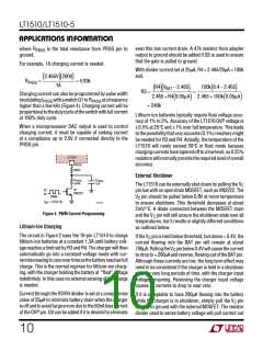
A fixed undervoltage lockout of 7V is built into the VCC pin.
Internal lockout is performed by clamping the VC pin low.
The VC pin is released from its clamped state when the VCC
pinrisesabove7V.Thechargerwillstartdeliveringcurrent
about 2ms after VC is released, as set by the 0.1µF at VC
pin. Higher lockout voltage can be implemented with a
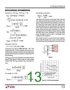
Zener diode (see Figure 3 circuit).
EMI considerations usually make it desirable to minimize
ripple current in the battery leads, and beads or inductors
maybeaddedtoincreasebatteryimpedanceatthe200kHz
switching frequency. Switching ripple current splits be-
tween the battery and the output capacitor depending on
theESRoftheoutputcapacitorandthebatteryimpedance.
If the ESR of COUT is 0.2Ω and the battery impedance is
raisedto4Ωwithabeadofinductor,only5%ofthecurrent
ripple will flow in the battery.
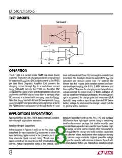
V
IN
V
D1
1N4001
V
Z
CC
Soft Start
V
LT1510
GND
C
The LT1510 is soft started by the 0.1µF capacitor on VC
pin. On start-up, VC pin voltage will rise quickly to 0.5V,
then ramp at a rate set by the internal 45µA pull-up current
and the external capacitor. Battery charging current starts
ramping up when VC voltage reaches 0.7V and full current
is achieved with VC at 1.1V. With a 0.1µF capacitor, time to
reach full charge current is about 3ms and it is assumed
that input voltage to the charger will reach full value in less
than 3ms. Capacitance can be increased up to 0.47µF if
longer input start-up times are needed.
2k
1510 F03
Figure 3. Undervoltage Lockout
The lockout voltage will be VIN = VZ + 1V.
For example, for a 24V adapter to start charging at 22VIN,
choose VZ = 21V. When VIN is less than 22V, D1 keeps VC
low and charger off.
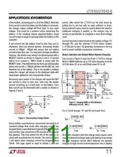
Charging Current Programming
In any switching regulator, conventional timer-based soft
starting can be defeated if the input voltage rises much
slowerthanthetime-outperiod.Thishappensbecausethe
switching regulators in the battery charger and the com-
puter power supply are typically supplying a fixed amount
of power to the load. If input voltage comes up slowly
compared to the soft start time, the regulators will try to
The basic formula for charging current is (see Block
Diagram):
2.465V
RPROG
IBAT = I
2000 =
2000
(
PROG)(
)
(
)
9

 Linear [ Linear ]