LT1510/LT1510-5
U
W U U
APPLICATIONS INFORMATION
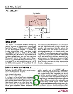
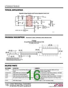
BAT
ADAPTER
OUTPUT
0.18Ω
SENSE
3.3V OR 5V
INTERNAL
D1
8
C1
R1*
SENSE
1N4148
0.1µF
R4
470k
1.6k
RESISTOR
LT1510
3
2
–
7
NEGATIVE EDGE
TO TIMER
LT1011
GND
+
4
1
R2
560k
D2
1N4148
R1(V
(R2 + R3)(0.18Ω)
)
R3
430k
BAT
* TRIP CURRENT =
1510 F06
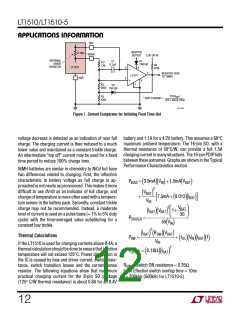
Figure 7. Current Comparator for Initiating Float Time-Out
battery and 1.1A for a 4.2V battery. This assumes a 60°C
maximum ambient temperature. The 16-pin SO, with a
thermal resistance of 50°C/W, can provide a full 1.5A
charging current in many situations. The 16-pin PDIP falls
between these extremes. Graphs are shown in the Typical
Performance Characteristics section.
voltage decrease is detected as an indication of near full
charge. The charging current is then reduced to a much
lower value and maintained as a constant trickle charge.
An intermediate “top off” current may be used for a fixed
time period to reduce 100% charge time.
NiMH batteries are similar in chemistry to NiCd but have
two differences related to charging. First, the inflection
characteristic in battery voltage as full charge is ap-
proached is not nearly as pronounced. This makes it more
difficult to use dV/dt as an indicator of full charge, and
change of temperature is more often used with a tempera-
ture sensor in the battery pack. Secondly, constant trickle
charge may not be recommended. Instead, a moderate
level of current is used on a pulse basis (≈ 1% to 5% duty
cycle) with the time-averaged value substituting for a
constant low trickle.
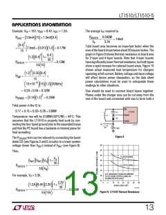
PBIAS = 3.5mA V +1.5mA V
(
)(
)
IN
(
)
BAT
2
)
V
(
BAT
+
7.5mA + 0.012 I
(
)( BAT
)
]
[
V
IN
2
)
VBAT
30
I
(
V
1+
BAT)(
BAT
PDRIVER
=
55 V
(
)
)
IN
2
I
R
V
(
BAT) ( SW)(
BAT
Thermal Calculations
PSW
P
=
+ t
(
V I
f
OL)( IN)( BAT)( )
V
IN
If the LT1510 is used for charging currents above 0.4A, a
thermal calculation should be done to ensure that junction
temperature will not exceed 125°C. Power dissipation in
the IC is caused by bias and driver current, switch resis-
tance, switch transition losses and the current sense
resistor. The following equations show that maximum
practical charging current for the 8-pin SO package
(125° C/W thermal resistance) is about 0.8A for an 8.4V
2
= 0.18Ω I
(
)( BAT
)
SENSE
RSW = Switch ON resistance ≈ 0.35Ω
tOL = Effective switch overlap time ≈ 10ns
f = 200kHz (500kHz for LT1510-5)
12

 Linear [ Linear ]